ESP32 is one of the microcontrollers for IoT applications par excellence. Created and manufactured by Espressif, it is currently the microcontroller of this compañy most used by the community, it is widely used for both educational and industrial development due to its great versatility, reliability and very low cost.
This Repository contains the source code and the steps to follow to be able to make ESP32 Microcontroller read sensor data and send it, in an organized way, to the Tangle (DLT) of the IOTA Network through the Streams layer.
This is the list of Sensors/Modules that you can connect and it will be recognized immediately.
- BME280 (Bosch) - Temperature, Humidity and Pressure sensor. -> Connected by I2C Bus via: GPIO33/SDA and GPIO32/SCL --- Be careful with the supply of this sensor, the BM280 is powered with 3.3V, if your module does not have a voltage regulator (some modules do not have it) the sensor can be damaged if you supply 5V.
- MPU6050 (InvenSense-TDK) - Acelerometer and Gyroscope 6-axis. -> Connected by I2C Bus via: GPIO33/SDA and GPIO32/SCL.
- BH1750 (ROHM) - Ambient Light Sensor. -> Connected by I2C Bus via: GPIO33/SDA and GPIO32/SCL.
- Generic Adjustable Sound Sensor with digital output (like KY038 Module) - -> Digital Signal on GPIO21, GPIO22 to GND (to enable sound data collection).
- Also, you can connect a Green LED in GPIO2 that blink when the data is sent to the Tangle, and a Red LED in GPIO15 that will Blink in a certain way when it detects certain errors (totally optional)
The following diagram explains how each sensor of our stack must be connected to the ESP32 pins. The "NodeMCU-32s" development board has been used in this diagram, which contains the ESP32 microcontroller. However, any development board that contains the ESP32 microcontroller can be used.

It is not necessary to have all the sensors listed here, the code is able to detect which sensors were connected. In the case of not connecting any sensor, the only real data that will be displayed on the Tangle will be the Internal Temperature of ESP32.
IMPORTANT NOTE: Espressif has deprecated the ESP32's internal temperature sensor a few years ago, as it has proven not to be a very accurate measurement. However we will use it as a minimum unit of information to be able to send data to the Tangle without having sensors connected. Please keep this in mind, so this value should not be taken into account for critical applications.
This repository uses the Iot2Tangle C Core devices adapted for ESP32-FreeRTOS offered in the official Espressif Toolchain ESP-IDF SDK. Once the SDK is installed you will have all the tools to compile and download the program on your ESP32.
The easiest way to install ESP-IDF and their prerequisites is to download the ESP-IDF Tools Installer from this URL: https://dl.espressif.com/dl/esp-idf-tools-setup-2.3.exe
Just follow the steps and you will have the official Espressif SDK Toolchain installed on your computer.
To check other methods, the following page is suggested: https://docs.espressif.com/projects/esp-idf/en/latest/esp32/get-started/windows-setup.html
Prerequisites of ESP-IDF SDK:
sudo apt update
sudo apt install git wget flex bison gperf python python-pip python-setuptools cmake ninja-build ccache libffi-dev libssl-dev
It is recommended to install the stable version: ESP-IDF v4.1, you can download it from here:
git clone -b v4.1 --recursive https://github.com/espressif/esp-idf.git
Now install the SDK, this may take a while:
cd ~/esp-idf
./install.sh
. ./export.sh
After doing this last step do not close the shell, as we will compile and flash from here. If you close the shell you will have to do the previous step again.
You can download the repository directly from Github, or from shell or Command Prompt with the following command:
git clone https://github.com/iot2tangle/ESP32.git
cd ESP32/BLE-sender
The config.h file is in the directory 'ESP32/BLE-sender/main' of the repository.
This step is not as important as in projects that use WiFi, since in this case we must not connect to any network, the same device is a BLE server and the Gateway will have to READ the device data.
In this file we can configure the NAME of the device with which the BLE server will be named, enable or disable Sensors and finally set the local data update interval, unlike HTTP or MQTT senders, this interval only updates the data locally (therefore it can be smaller than in the named cases), since the sending data interval to the Tangle is determined by the BLE Gateway, not by the ESP32).
/* Device */
const char* id_name = "ESP32-BLE-I2T";

/* Enable Sensors */
bool isEnable_Environmental = true;
bool isEnable_Acoustic = true;	/*                     true: Enable  --  false: Disable                            */
bool isEnable_Light = true;		/* If the sensor is disabled the data about it will not be displayed in the Tangle */
bool isEnable_Accelerometer = true;
bool isEnable_Gyroscope = true;

/* Interval of time for Data Update */
long interval = 6;    /* Time in seconds */
Remembering to have the ESP-IDF Toolchain open, and you make sure you are at the root of the BLE-sender folder run the following command:
idf.py build
If the compilation was correct it should read: Project build complete.
Now make sure you have ESP32 connected to your computer, and know what COM port it is connected to. (You can see this in 'Device Manager').
Then run the following command that will start flashing the firmware. (You will probably have to press the reset button on your ESP32 development board, even several times for it to recognize the board.)
idf.py -p COM1 flash # COM1 is an Windows port example, you must put your port. In Linux /dev/ttyUSB0 is an example, and in macOS: '/dev/cu'
Upon completion, the firmware is downloaded to your ESP32. If the I2T Streams BLE Gateway is configured correctly (we will explain this next), you will be sending data to Tangle via Streams.
If configured correctly, ESP32 will create a BLE Server to which the BLE Gateway can connect to READ the data every time interval set in the Gateway configuration. However, you may want to verify that it is running on ESP32.
The code continuously sends information out the serial port, so it can read the serial port to see what is happening and detect errors.
You can use the 'Arduino Serial Monitor' for this, but we recommend using the following software:
Open Command Prompt.
Configure the Baud Rate of the port to 115200 bps:
mode COM1: baud=115200
Read the serial port:
copy COM1: con:
Install cu Monitor. It is an excellent shell monitor and very useful.
sudo apt install cu
Run cu Monitor:
cu -l /dev/ttyUSB0 -s 115200
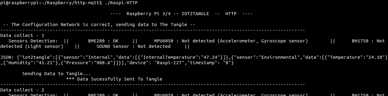
The following screenshot is a reading of the Serial Port, you should see something like this:
You may also want to read the data directly from the BLE Server. For this there are Free OpenSource software.
We recommend nRF Connect (free OpenSource software) of NordicSemiconductor available in Desktop: on Windows, macOS and Linux. And in Mobile: on Android and iOS (The mobile version is very simple and more comfortable to debug). It only needs to be connected to the ESP32 BLE Server and it will be able to read the data from the sensors found in the Characteristics Values
Note that when you have a device connected to ESP32 BLE the Gateway will not be able to read the data.
In the event that you do not have any I2T Stack Sensors sensor, you will only see the Internal Temperature data of the ESP32. If you like, you can compile with a 'flag' that assigns hardcoded values to all available data. This way you can see numerically more complete outputs on the Tangle.
You just need to modify the file ESP32/BLE-sender/main/CMakeLists.txt and add the -DTEST flag.
add_definitions (-DESP32 -DMICROCONTROLLER -DSHELLPRINT -DTEST)
This way, you can see data in the Tangle as if you had all the sensors.
Install Rust if you don't have it already. More info about Rust here https://www.rust-lang.org/tools/install
curl --proto '=https' --tlsv1.2 -sSf https://sh.rustup.rs | sh
Make sure you also have the build dependencies installed, if not run:
sudo apt update
sudo apt install build-essential pkg-config libssl-dev libdbus-glib-1-dev
Get the Streams MQTT Gateway repository https://github.com/iot2tangle/Streams-BLE-gateway
git clone https://github.com/iot2tangle/Streams-BLE-gateway
cd Streams-BLE-gateway
Here you will get the address of your ESP32 BLE device (similar to the MAC address). You should make a note of it, as we'll put that address in the config.json file later in the next step.
Run the following to scan and get the address of your ESP32.
cargo run --release --bin scan
Navigate to the root of Streams-MQTT-gateway directory and edit the config.json and copy the address obtained in the previous step.
Here you can also configure the time interval with which the GW will read the data to the BLE Devices and send the data to the Tangle, also the node, amoung other settings.
{
    "device_ids": [
        "XX:XX:XX:XX:XX:XX"
    ],
    "reading_interval": 30,
    "node": "https://nodes.iota.cafe:443",
    "mwm": 14,
    "local_pow": false
}
Run the Streams BLE Gateway:
cargo run --release --bin ble-gateway
This will compile and start the Streams BLE Gateway. Note that the compilation process may take from 3 to 25 minutes (Pi3 took us around 15/25 mins, Pi4 8 mins and VPS or desktop machines will generally compile under the 5 mins) depending on the device you are using as host. You will only go through the compilation process once and any restart done later will take a few seconds to have the Gateway working.
Once started, the Channel Id will be displayed, and the gateway will be open waiting for data to send to the Tangle.

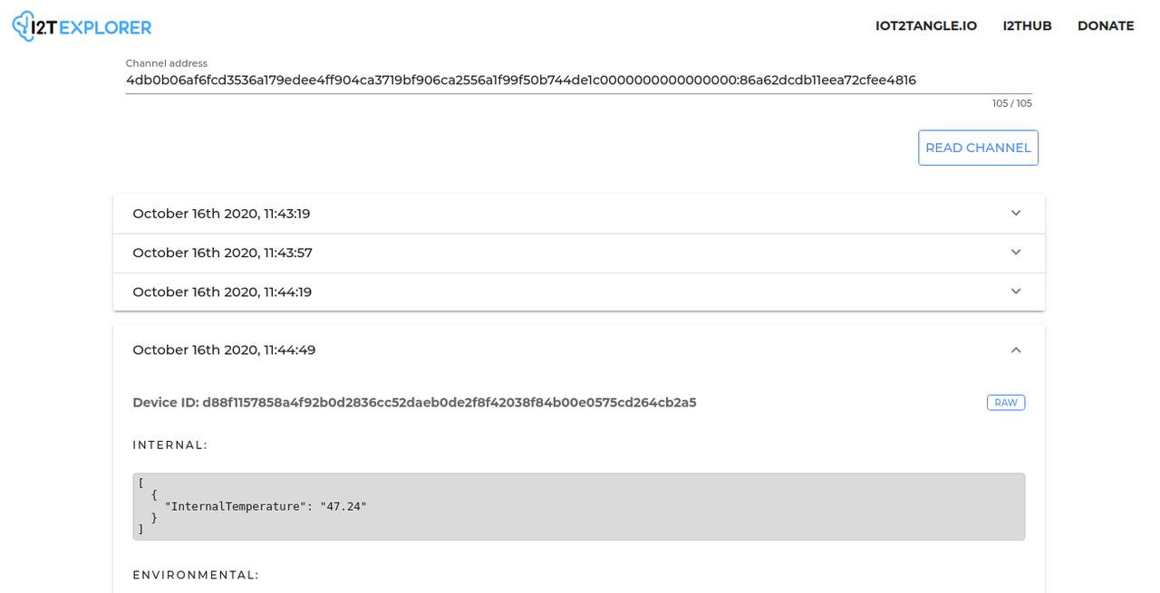
You can read the received messages directly from the I2T Explorer: https://explorer.iot2tangle.io/ using the Channel Id printed by the Gateway in shell.
For inquiries, improvements or errors detected, please start an issue in this repository.