Skip to content
New issue

Have a question about this project? Sign up for a free GitHub account to open an issue and contact its maintainers and the community.

By clicking “Sign up for GitHub”, you agree to our terms of service and privacy statement. We’ll occasionally send you account related emails.

Already on GitHub? Sign in to your account

[examples] SVG Straight-Skeleton #423

Open
dennemark opened this issue Oct 22, 2023 · 3 comments
Open

[examples] SVG Straight-Skeleton #423

dennemark opened this issue Oct 22, 2023 · 3 comments

Comments

@dennemark
Copy link

Hi,
I am opening an issue to provide an example on how to generate a Straight-Skeleton via SVG. It does not contain the actual lines of the straight skeleton, but some tricks on how to generate it as a height map. It includes boundary as well as a hole.

Feel free to use it as a HowTo thi.ng!

Would have liked to try to use geom-isolines to get a vector representation of it, but it seems its better to use hiccup-canvas instead. So there are still possibilities to extend the example. But for the current use, it should work.

SVG Polygons
KBiA27YD5O
Polygons with Gradients
54gtmYI9Tc
Polygons with Darken-Filter
RYgAWHnbT7
Polygons with Mask - Straight Skeleton
firefox_Fdi4JvDEpe

index.ts

import * as svg from "@thi.ng/hiccup-svg";
import { $compile } from "@thi.ng/rdom";
import * as vec from "@thi.ng/vectors";

/**
 * end result will be nearly a straight skeleton
 * that is generated via svg gradients, filters and masks
 */

/** we only create gradients up to a specified max length */
const MAX_LENGTH = 300;

/**
 *
 * straight skeleton parts (boundary or hole)
 *
 * we will create polygons for each line
 * they will be extrusions inside to the polygon
 * all getting a gradient pointing in that same direction
 * afterwards we will use a darken filter
 * this way, only the darkest pixel will be shown
 * and the result will look pretty much like a straight skeleton
 *
 * however on concave corners
 * we have an edge case.
 * our extrusion wont go around the corner,
 * but we can use a bisect vector to change the offset
 * direction of the extrusion.
 *
 *
 * so we offset the line perpendicularly
 */
const createStraightSkeletonPart = (path: vec.Vec[]) => {
	/**
	 * we add the first three points to the end, so we can easily cycle through points
	 * to create bisect vectors for each line
	 */
	const cyclicPath = [...path, ...path.slice(0, 3)];

	const svgPolys = path.map((_, i) => {
		/** get points for bisecting vectors */
		const prev = cyclicPath[i];
		const start = cyclicPath[i + 1];
		const end = cyclicPath[i + 2];
		const next = cyclicPath[i + 3];
		const dir = vec.asVec2(vec.normalize([], vec.sub([], end, start)));
		/** we create bisect vectors at start and end
		 * currently they have a scale of MAX_LENGTH
		 * could be improved by offseting to MAX_LENGTH perpendicular to start-end line
		 * via some trigonometry if we get the correct angle.
		 */
		const cross = vec.normalize([], [-dir.y, dir.x], MAX_LENGTH);

		const bisectStart = vec.cornerBisector2(
			null,
			prev,
			start,
			end,
			MAX_LENGTH
		);
		const bisectEnd = vec.cornerBisector2(
			null,
			start,
			end,
			next,
			MAX_LENGTH
		);

		/** if our bisect vectors are on concave corners
		 * we will use them to offset the start / end
		 * otherwise we just use the cross vector
		 */
		const bisectAngleStart = vec.angleBetween2(dir, bisectStart);
		const bisectAngleEnd = vec.angleBetween2(dir, bisectEnd);
		const startOffset = vec.add(
			[],
			start,
			bisectAngleStart > Math.PI / 2 ? bisectStart : cross
		);
		const endOffset = vec.add(
			[],
			end,
			bisectAngleEnd < Math.PI / 2 ? bisectEnd : cross
		);

		/** we need to rotate the final polygon,
		 *  since our linear-gradient goes from top to bottom.
		 *  we rotate our points so start and end point are in line with [1,0]
		 * afterwards we rotate the polygon back into position
		 * */
		const radiansAngle = vec.angleBetween2(dir, [1, 0], false);
		const degreesAngle = (radiansAngle * 180) / Math.PI;
		const rotatedPts = [start, end, endOffset, startOffset, start].map(
			(pt) => {
				return vec.rotateAroundPoint2([], pt, start, radiansAngle);
			}
		);

		/** create svg polygon using our gradient
		 * and rotating it back in position
		 */
		return svg.polygon(rotatedPts, {
			fill: "url(#gradient)",
			transform: `rotate(${-degreesAngle})`,
			"transform-origin": `${start.x} ${start.y}`,
		});
	});
	return svgPolys;
};

// boundary has winding order clock wise
// geojsons standard might be other way around... 🙈
const boundary = [
	[50, 50],
	[400, 50],
	[400, 400],
	[600, 600],
	[400, 600],
	[50, 400],
].map((v) => vec.asVec2(v));
const boundarySkeletonPart = createStraightSkeletonPart(boundary);
// hole has winding order counter clock wise
const hole = [
	[200, 300],
	[200, 400],
	[300, 400],
	[300, 300],
].map((v) => vec.asVec2(v));
const holeSkeletonPart = createStraightSkeletonPart(hole);

/**
 * now we create our svg
 */
$compile(
	svg.svg(
		{ width: "100%", height: "100%", viewBox: "0 0 700 700" },
		/**
		 * add definition for linear gradient
		 */
		svg.defs(
			svg.linearGradient(
				"gradient",
				[0, 0],
				[0, 1],
				[
					[0, "black"],
					[100, "white"],
				]
			)
		),
		/**
		 * add blend mode for polygons
		 */
		["style", {}, "polygon {mix-blend-mode: darken;}"],
		/**
		 * mask skeleton parts by the boundary
		 */
		["mask", { id: "mask" }, svg.polyline(boundary, { fill: "#fff" })],
		svg.group(
			{
				mask: "url(#mask)",
			},
			...boundarySkeletonPart,
			...holeSkeletonPart
		),
		svg.polyline(boundary, { strokeWidth: 1, stroke: "#f00" }),
		/**
		 * and now lets fill our hole and we are done
		 */
		svg.polyline(hole, { strokeWidth: 1, stroke: "#f00", fill: "#fff" })
	)
).mount(document.getElementById("app"));
@postspectacular
Copy link
Member

Danke, danke @dennemark! Will take a look later today and report back... 🙏🤩

@postspectacular
Copy link
Member

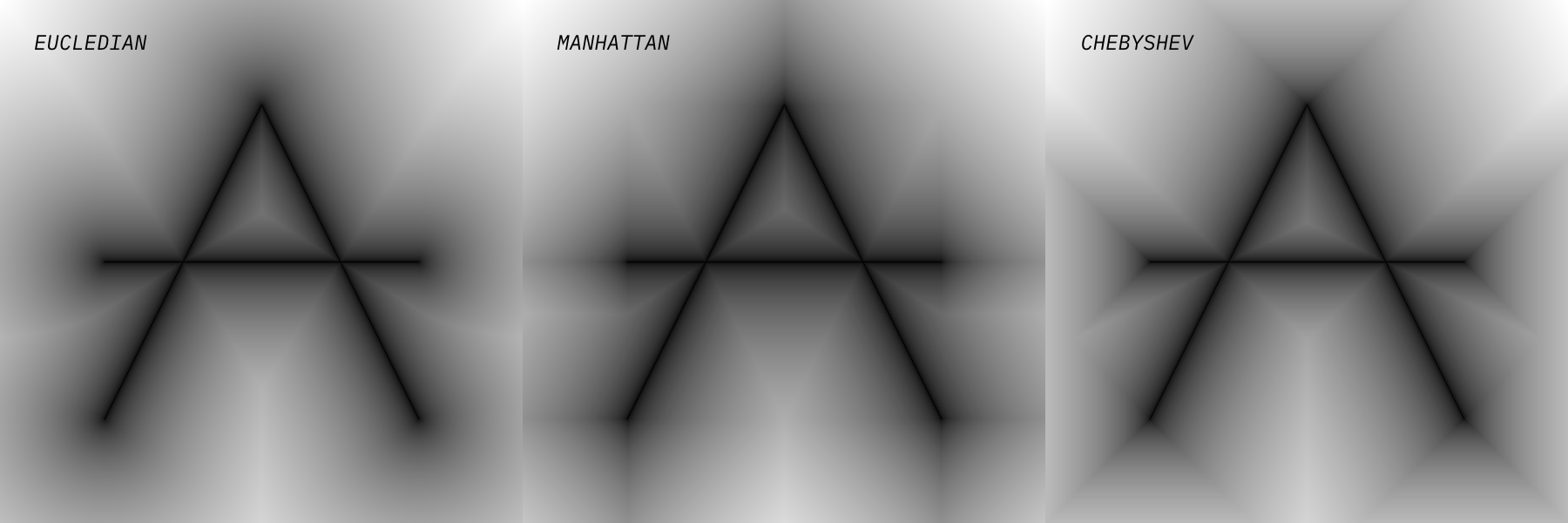
@dennemark Sorry for the delay about getting back to you about your straight skeleton. Not forgotten about it. Also, if you're not after extracting the actual geometry of the skeleton, you might find the https://thi.ng/distance-transform package a more simple alternative approach...

thi.ng/distance-transform readme examples

@dennemark
Copy link
Author

🙄thi.ng offers too many algorithms! Super useful!
Distance-transform should be combinable with geom-isolines, I guess.

My approach definitely has some weaknesses, but since I know every line, I can scale the gradient for each of them differently, allowing me to make it weighted. Though I would have to add more gradients in that case.

Sign up for free to join this conversation on GitHub. Already have an account? Sign in to comment
Labels
None yet
Projects
None yet
Development

No branches or pull requests

2 participants