Smaller CNCs such as the CNC3018 use GRBL as the controller.
However, for CNC3040 and above, Mache 3/4, which is older in design and less user-friendly, is often used. Here we show how to build a CNC3040 system with GRBL/wifi.
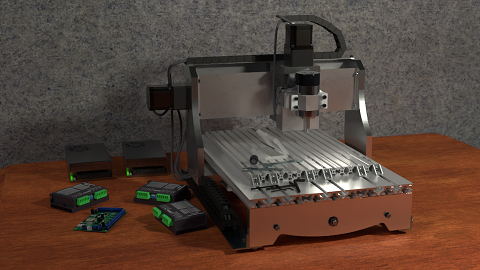
Required
- CNC DIY frame. 3Axis CNC3040Z without motor
- 2 motor. Dual 8mm shaft NEMA23 motor, 23HS5628-SZ for X/Z axis
- 1 motor. Mono 8mm shaft NEMA23 motor, 23HS5628-8mm for Y axis
- 3 coupling, 8mm x 8mm
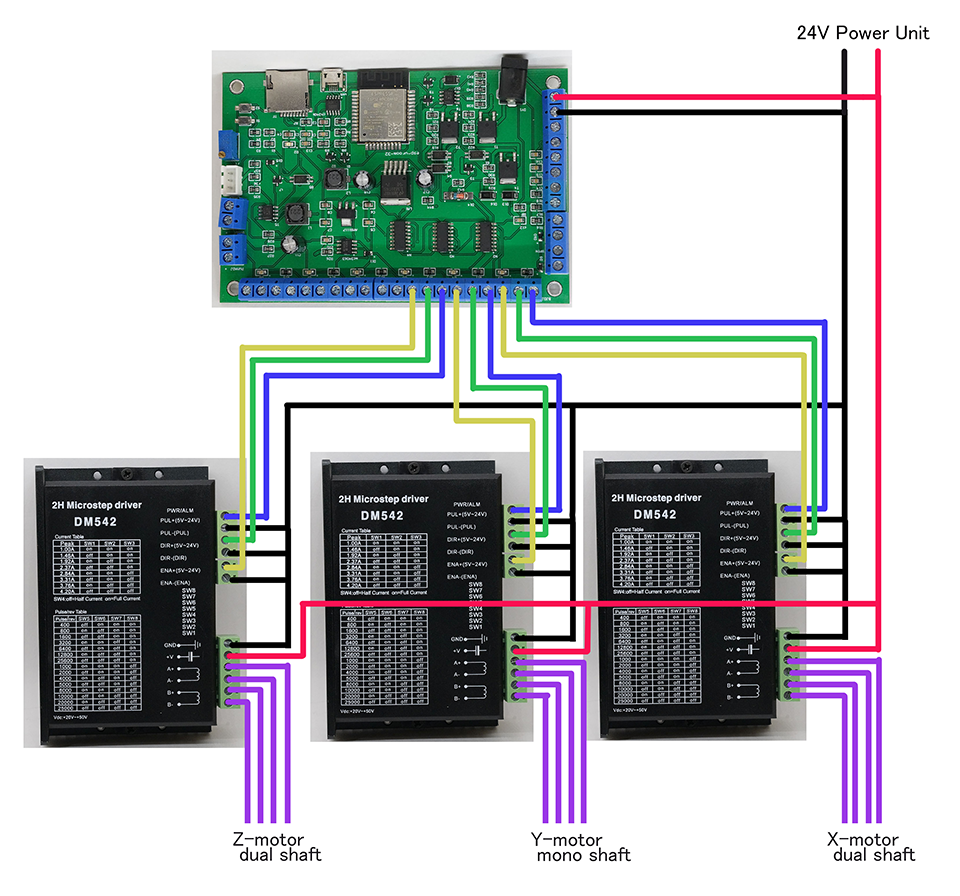
- 3 driver. DM542
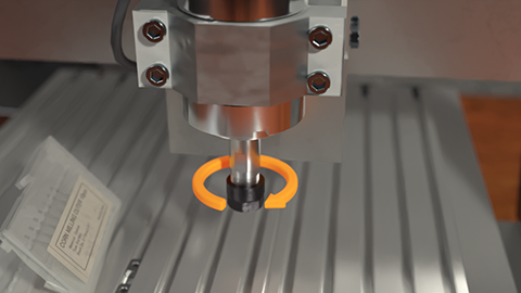
- Spindle. BLDC 300W spindle with driver, holder, speed meter and ER11
- GRBL board. 32bit 6axis CNC card
- Power unit. 24V 360W-Quiet for motors
- Power unit. 36V 400W-Quiet for spindle
- Shielded cable. 4core 18AWG 10m for motors
- Shielded cable. 3core 18AWG 5m for spindle
- microSD card. 1GB
Optional
- Ribon cable. 28AWG 5m
- XH2.54 connector. 230Pcs XH2.54 for motors
- Ferrule connector. Many types of 340pcs for GRBL board and drivers
- Terminal connector. OT-3A for power units
- Drag chain. inner size 10x20mm 2m
- Cable tie. 3x100mm
- 3D printer
** Shielded cable is required. Unshielded cables will cause motor errors such as stalling.
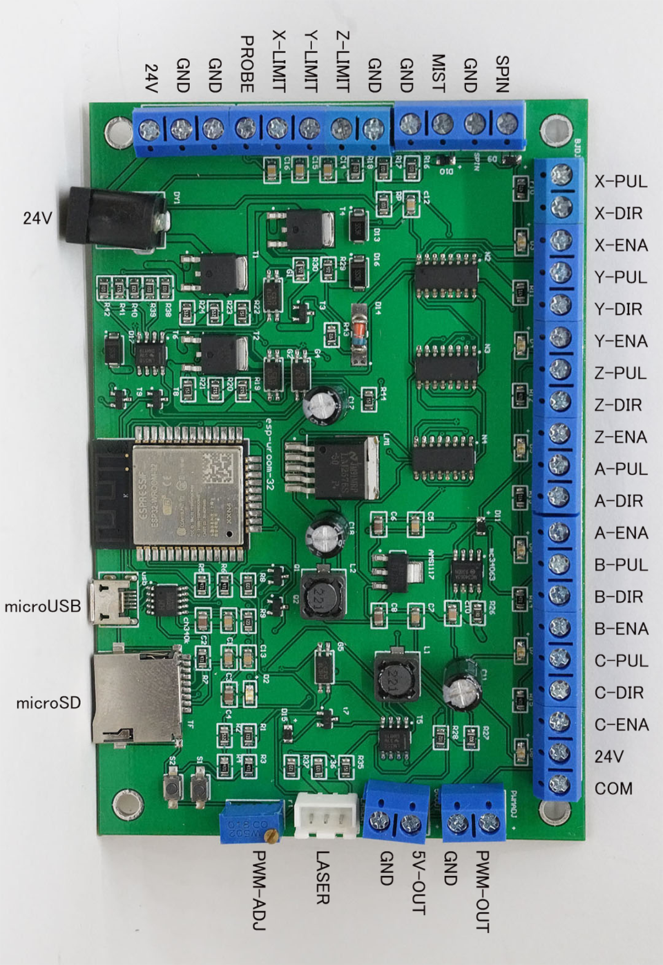
GRBL board, 32bit 6axis CNC card, is equipped with an EPS32 and has a standard FluidNC(GRBL for ESP32) firmware burned in.
Wireless connectivity is supported. Before wiring, first check this operation.
This board is compatible with 12-24V power supply, 36V is not support.
Connect to 24V power supply. Then the on-board LED glows momentarily and ESP32 operates as an access point mode.
Enable the wireless on your smartphone or PC and you can find the SSID GRBL_ESP. The password is 12345678.
Once connected to the GRBL board, access http://192.168.100.101/ in your browser.
If connection failed, try another URL http://192.168.100.104/ , http://192.168.101.100/ or so on. Or, open a command prompt on your PC and run arp -a to identify the IP address = URL.
GRBL board, 32bit 6axis CNC card, is equipped with an EPS32 and has a standard FluidNC(GRBL for ESP32) firmware burned in.
- PUL/DIR/EN pins are 5V high/low output. DO NOT connect to over 5V voltage power supply.
- High voltage of PWM-OUT is adjustable.
- Both 24V pins are directly connected. Therefore, they can be used for both IN and OUT.
DM542 is stepper motor driver.
This is compatible with 20-50V power supply.
- PUL-/DIR-/ENA- pins are connected to GND.
- If you want to keep motor always on, connect both ENA+/ENA- pins to GND.
- When wiring more than 2m, use shileded cable, or motor trouble will occur.
Dual 8mm shaft NEMA23 motor, 23HS5628-SZ for X/Z axis
Mono 8mm shaft NEMA23 motor, 23HS5628-8mm for Y axis
23HS5628 is 56mm height, 2.8A, 126N.cm.
- Pin assignments vary by product, so check with a tester.
The direction of motor rotation is not important because it can be changed by software.
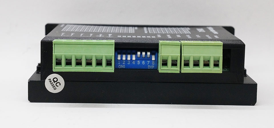
DIP switch setting of DM542 is 1.0A, Full Current, 25600 steps, on on on on off off off on.
The motor's rated current is 2.8 A, but it is better to keep the value small unless it is necessary because it generates more heat.
CNC3040Z's ball screw are SFU1605 with 5mm pitch.
In other words, the 25600 steps in DM542 are 5mm, so 5120 steps/mm.
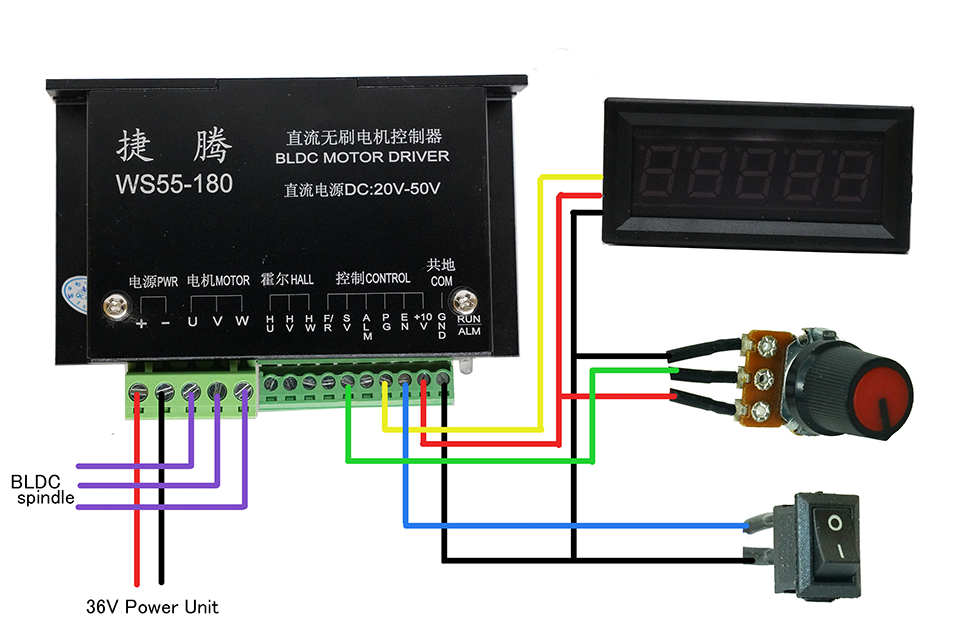
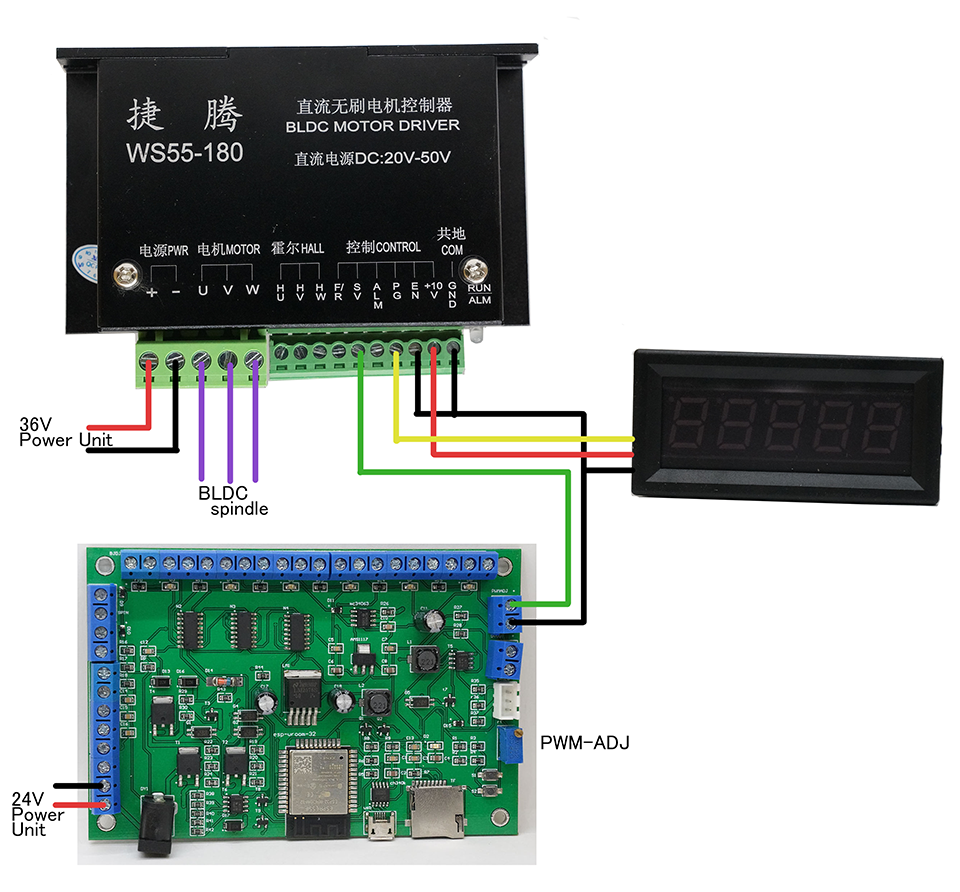
WS55-180 is brushless spindle motor driver.
RPM can be manually set by volume (10k ohm) or automatically adjusted by G-CODE.
For automatic control, turn the PWM-ADJ volume to 0-10V PWM output before wiring.
To adjust, access GRBL board with a browser. Set speed value 1000 in spindle tab and press the On Fwd button. Then voltage is output to PWM-OUT pin. Turn the PWM-ADJ volume so that the output is 10V.
The direction of spindle rotation is important. Be sure to set correctly by change order U/V/W to U/W/V, etc., if in reverse.
-
Manual control
-
Automatic control
-
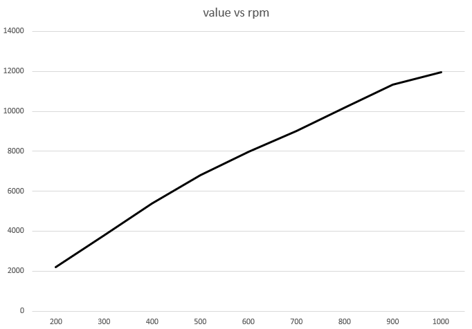
Value in G-CODE vs RPM (no load)
| value | rpm |
|---|---|
| 200 | 2200 |
| 300 | 3800 |
| 400 | 5400 |
| 500 | 6800 |
| 600 | 8000 |
| 700 | 9200 |
| 800 | 10200 |
| 900 | 11300 |
| 1000 | 12000 |
GRBL/FluidNC setting
To change the GRBL configuration, follow the steps below.
- Access GRBL board with browser
- Download the configuration file from GRBL board to your PC
- Edit the configuration file on your PC
- Upload the file to GRBL board
- Restart GRBL board
Here is my CNC3040Z configuration file
The various port settings on the GRBL board are not problm as default.
The following items are important
steps_per_mm: of X/Y/Z set to 5120.000.
max_rate_mm_per_min: of X/Y/Z set to 500.000.
homing:cycle: of X/Y set to 1.
homing:cycle: of Z/A/B/C set to 0.
max_travel_mm: of X set to 300mm.
max_travel_mm: of Y set to 400mm.
max_travel_mm: of Z set to 100mm.
start:must_home; set to false.
When the direction of the stepping motor is reverse rotation, edit direction_pin:.
Just add :low to reverse rotation, ex. direction_pin: I2SO.4 to direction_pin: I2SO.4:low
GRBL board, 32bit 6axis CNC card, has no port for offline controller.
But you can control via wifi. Although it is not an offline controller, it can be used like an offline controller.
- With smart phone, access GBRL board with browser.
- Open
Tablettab. - You can control CNC via wifi.
GRBL board, 32bit 6axis CNC card, has a microSD slot.
Stand-alone processing is available by uploading g-code file in microSD. Upload can do via wifi.
- Access GBRL board with browser.
- Upload g-code file to microSD. File extension is like
.nc. - Set
GRBL Reports:toAuto - Set endmill to the spindle.
- Move spindle head to start position.
- Press
⌀XYZABCbutton, work coordinates set to zero. - Start CNC machining.
If you want to abort, press pause and refresh button.
GRBL board, 32bit 6axis CNC card, has a microUSB connector.
It supports HID/serial protocol. So you can control CNC via serial port.
GRBL board, 32bit 6axis CNC card with firmware of FluidNC, supports multiple wireless protocol.
So you can control CNC via wifi, and by using a wireless-serial port bridge with virtual serial port, it can be controlled like as wired connected CNC.
- Bluetooth/serial (not recommended)
- WebSocket via wifi (not recommended)
- Telnet via wifi (recommended)
Bluetooth is for exclusive use with wifi. Therefore, enabling bluetooth is not recommended since wifi is not available.
WebSocket is also used for control by browsers. This is not recommended as the connection is a bit unstable and can be dropped.
So telnet/wifi is recommended.
The following is an example of a setup is with Candle for windows.
- Install virtual serial port com0com.
- In setup of com0com, check
enumulate baudrateand add one pair of virtual serial port, COM19 & COM20. - Download latest version of IvyTcp2Serial and extract.
- Create shortcut file of
IvyTcp2Serial.exe. - Right click shortcut file and open property.
- Edit shortcut link
IvyTcp2Serial.exetoIvyTcp2Serial.exe /server=192.168.100.101 /port=23 /comport=COM19 /baudrate=115200 /parity=none /stopbits=1. IP address and comport should be changed according to your environment. - Execute IvyTcp2Serial with serial, and connected to CNC via wifi/telnet.
- Execute Candle with serial port like
COM20. - At first, send command to CNC,
$Report/Interval=50. This is because the default frequency of coordinate report is low. - Now you can control CNC via wifi with Candle.
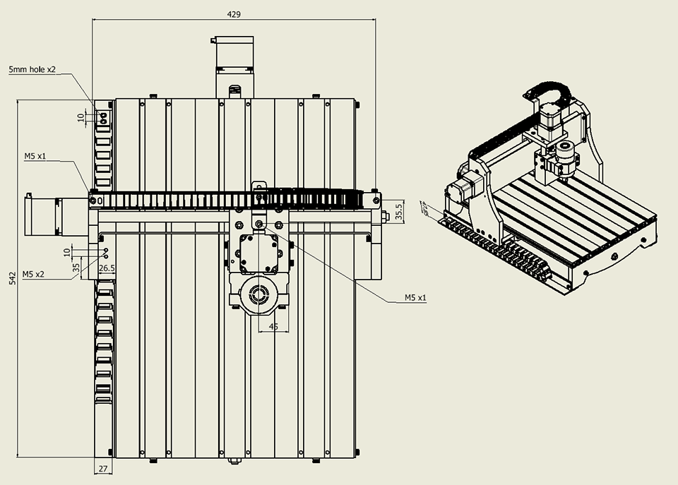
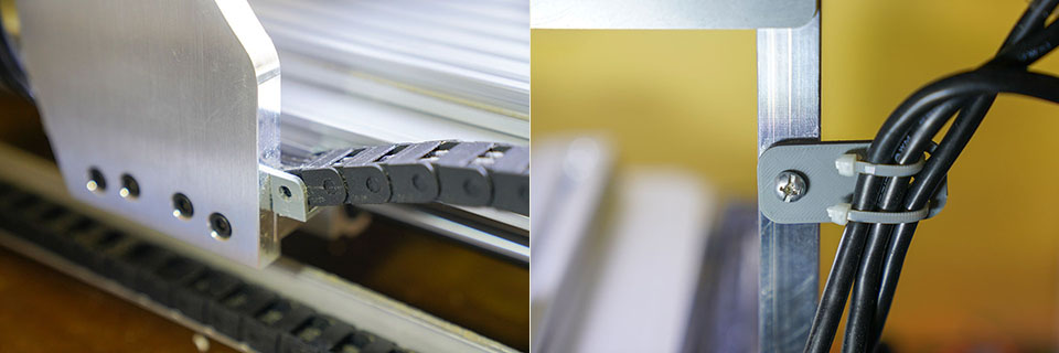
CNC3040Z has several screw holes for cable management and comes with an adapter to secure the drag chain.
However, we don't know which drag chain would fit perfectly. So, we made our own adapter with 3D printer.
Usable drag chain is inner size 10x20mm, close type.
Since there are slight differences in size between drag chain products, it is better to design your own 3D printed parts without using stl.
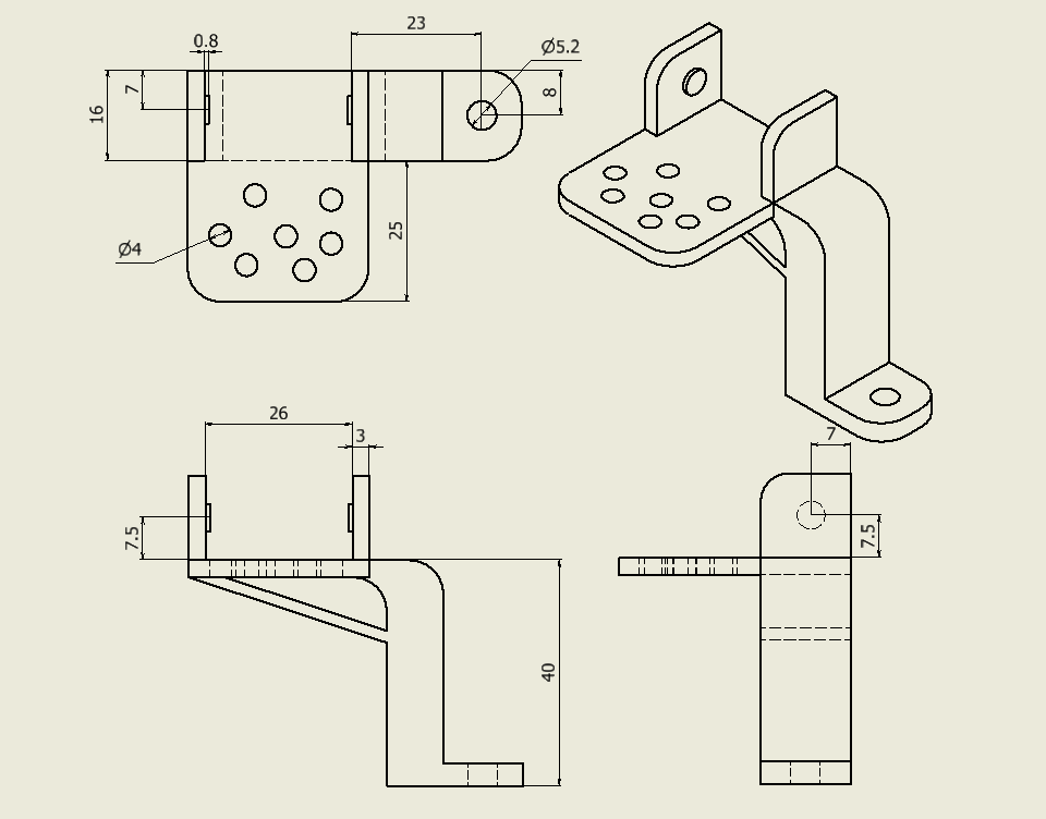
The required length of the X axis drag chain is about 60cm.
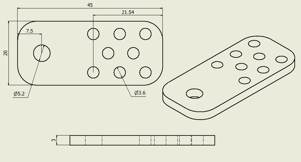
Stl file of drag chain end cap for X axis type1
Stl file of drag chain end cap for X axis type2
Multiple holes are for cable tie 3x100mm
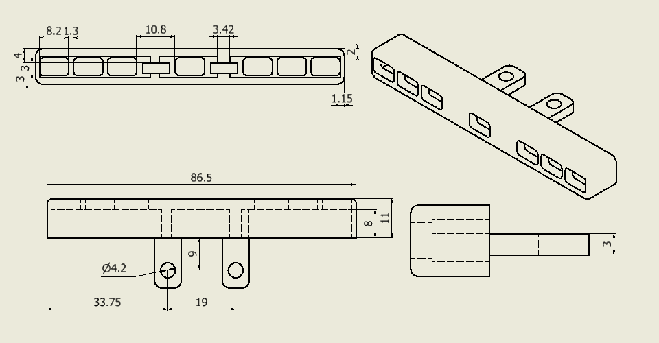
The required length of the Y axis drag chain is about 70cm.
The gap between the stage and the side panel is 26.5mm, which is a little narrow for a drag chain. Therefore, it is fixed in an irregular manner.
Stl file of drag chain end cap for Y axis
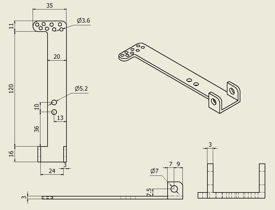
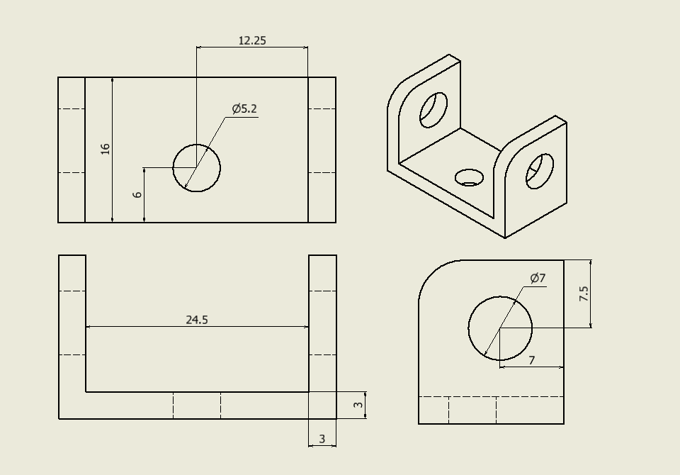
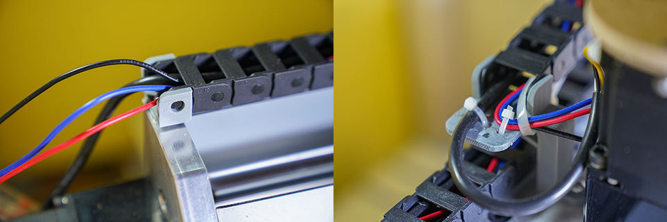
M5 screw holes are provided near the Y-axis motor. This is used to secure the cable between Y-axis and X-axis.
Stl file of cable adapter between Y and X
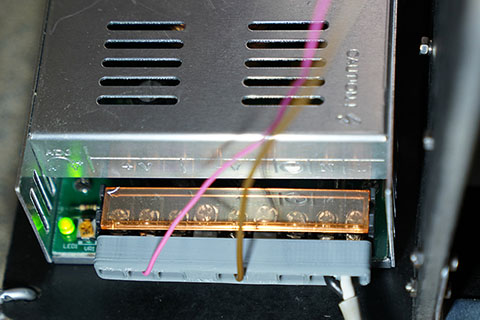
This CNC use 2 power units, 24V 360W-Quiet and 36V 400W-Quiet.
This power unit is easy to short-circuit because the terminals are exposed. Create a protective cover.
Stl file of Power unit terminal guard
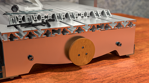
Knob on dual shaft motor make manual position adjustment easier.
So, for X/Z axis, It is better to use dual shaft motors, 23HS5628-SZ.
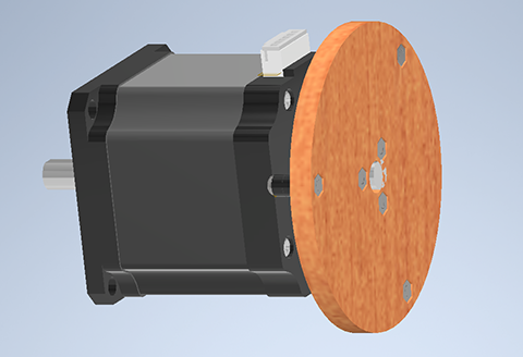
Parts list
- x1 dual 8mm shaft NEMA23 motor, 23HS5628-SZ
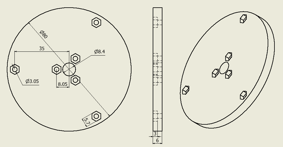
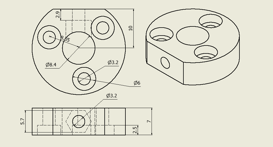
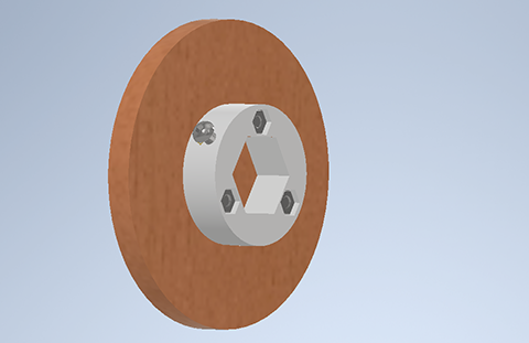
- x1 knob body, CNC machined 6mm thick MDF, STL file
- x1 knob adapter, 3D printed, STL file
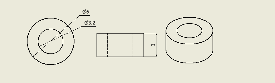
- x6 spacer for small knob, CNC machined 3mm thick acrylic board, STL file
- x4 M3-10mm screw
- x3 M3-12mm screw
- x7 M3 nut
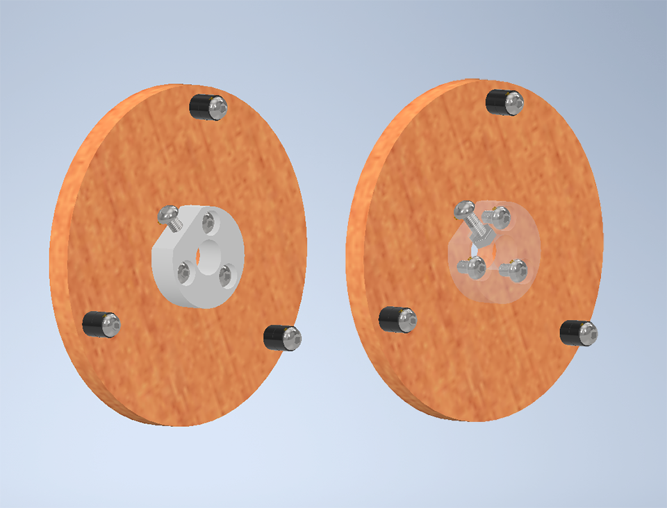
The Y-axis of CNC3040Z has ball bearing nut out. This nut is used to create the knob.
Parts list
- x1 knob body, CNC machined 6mm thick MDF, STL file
- x1 knob adapter, 3D printed, STL file
- x3 M3-12mm screw
- x1 M3-10mm screw
- x4 M3 nut
CNC3040Z has 360x545mm stage using 3 pcs of 20120.
This stage is common in CNC, but has some disadvantages such as wide groove spacing, necessity to use big screw for T-nut, etc.
Therefore, change to user friendly 20 alminium profile stage.
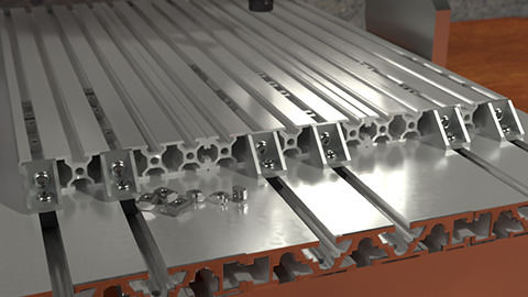
Parts list
- x3 20100 450mm
- x12 2020 corner bracket
- x12 T-nut M6
- x24 M3, T slide nut 20
- x24 M6 screw
20100 450mm has has holes in the side. The diameter of this hole is 4.2mm or 5.0mm, depending on products. Use M5 or M6 tap to make threaded hole.
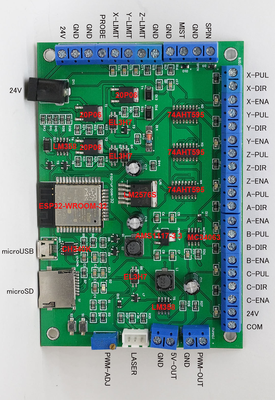
GRBL board, 32bit 6axis CNC card is not open source device. Threfore, schematic and specification are unknown.
Looking at the PCB... there is some famous chips. We have not followed the schematic, but we predict the approximate function from PCB layout.
- ESP32-WROOM-32: MPU module
- 74AHT595: 8bit shift register. X/Y/Z/A/B/C and maybe SPIN/MIST out is through this chip
- MC34063: DC-DC converter, 1.5A. Maybe for 5V-OUT
- AMS1117-3.3: 3.3V regulator. ESP32's power supply
- CH340K: USB-Serial bridge
- LM358 (up): opamp. Unknown
- LM358 (down): opamp. Maybe for PWM-OUT
- EL3H7: photo coupler. LIMIT/PROBE and maybe PWM for laser is isolated by this chip
- LM2576S: DC-DC converter, 3A. Maybe for laser power supply
- 20P06: P-ch power MOSFET. Unknown
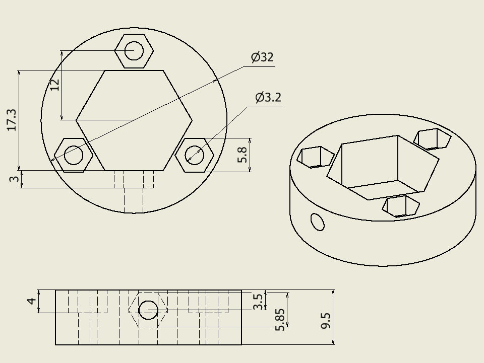
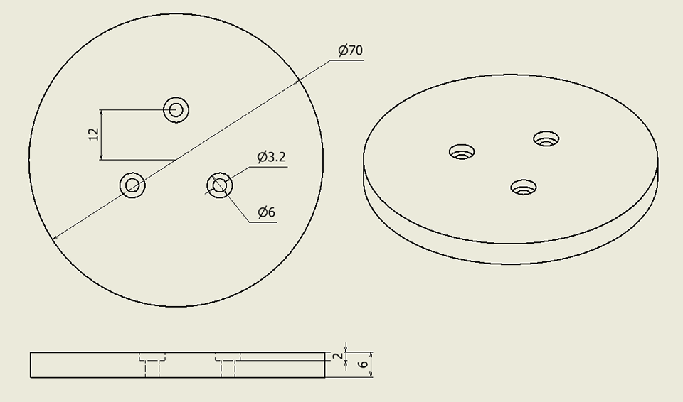
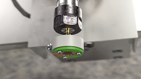
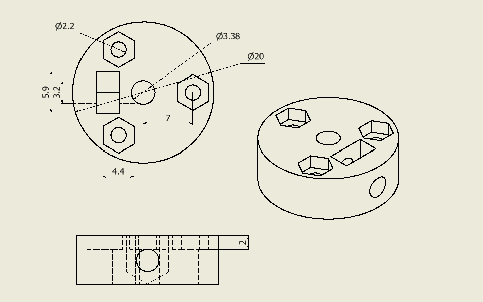
Simple probe using a tactile switch.
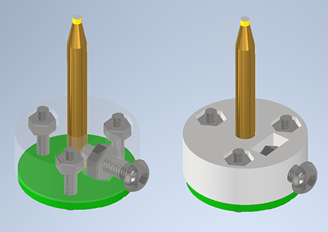
Parts list
- x1 Probe base, 3D printed, STL file
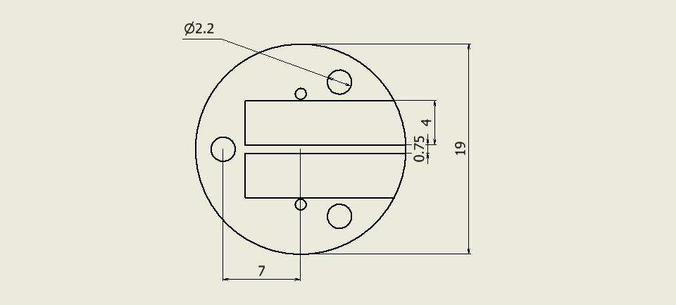
- x1 Bakelite single side PCB, DXF file
- x1 Tactile switch 2.0mm height
- x1 3.175mm broken endmill
- x1 M3-10mm screw
- x3 M2-10mm screw
- x1 M3 nut
- x3 M2 nut
Generally, PCB pattern cutting is done by generating gcode from gerber and cutting with V-cutter. However, for a simple board like this, it is easier to use general CAD and endmill.
In this case, we used 0.5mm corn endmill.
If you have any idea or suggestion, please add a github issue.