
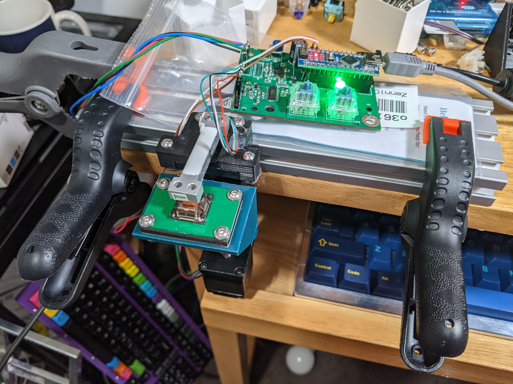
This is an open-source keyboard switch force-curve tester for MX-style switches. Gen 1 is currently operational, and force curves of various switches I've measure are in the Force curve measurements\ directory. Gen 2, which has a Geekhack IC for a potential future group buy and is meant to be more user friendly, is currently being prototyped.
This was designed specifically for MX switches to simplify the design and make everything cheaper and more compact, and since most of the switches I am curious about (as well as almost all new switches released today) use the MX form factor. In theory it could be adapted to test say, Alps or other discrete switches (it would need a different plate and switch holder). This is not as versatile as force-curve testers built around a test stand (like the one Haata built) and can't test arbitrary keyboards like that one, but it's much cheaper to build (I spent about $200 building this, and in theory this is buildable for ~$100 if one foregoes the custom PCB and order the parts from China)
This project is licensed under the CERN OHL-S (strongly reciprocal) license for the hardware designs and the software. This is a share-alike license, and if you modify the project files you are required to also open-source your modifications.
The force curve graphs themselves - the .ODS spreadsheets and the .PNG images of the graphs in the Force curve measurements\ folder - are licensed under Creative Commons CC-BY 4.0.
- A linear stage. I designed around this inexpensive $55 linear stage off Amazon. You can find what appear to be identical units on Aliexpress and elsewhere for less (if you get them from Aliexpress, make sure you buy the model with 1mm pitch (lead) on the leadscrew). Gen 2 will use the same linear stage.
- A stepper motor. The stepper motor serves two purposes - it moves the linear stage, and also keeps track of position to plot the X-axis of the force curve. Stepper motors, as long as they aren't stalled or skip steps, move a given amount based on the number of step commands sent, and lets me forego having to directly measure position. Instead, I can just count the number of steps sent to the stepper motor, since I know how much the stepper motor will move for a given number of steps. I used the included stepper motor in the linear stage above, which moves 1.8° per step (200 steps per full rotation). Combined with the 1mm lead leadscrew on the linear stage, a single step (without microstepping) in theory moves 0.005mm.
- A stepper motor driver. I used a Trinamic TMC2209 on Gen 1, and a generic StepStick-style module on Gen 2. Communication occurs using STEP/DIR control.
- A load cell, to measure the force on the switch. I used this 500g load cell from Sparkfun (it can be found on Aliexpress for slightly less).
- A load cell amplifier and ADC for reading the load cell and converting the readinging into a digital signal that can be easily read by the microcontroller. I used Avia's HX711 on both Gen 1 and Gen 2as Sparkfun made a module for it, and there is an Arduino library available for it. Gen 2 has provisions for SPI and I2C for potential future upgrades with faster and more expensive ADCs (e.g. Analog Devices AD7730).
- A microcontroller. On Gen 1 I used an Arduino Nano clone as I had one lying around. On Gen 2 I am using Adafruit's Feather RP2040.
There is also an RGBLED (on board on Gen 1, on the Adafruit RP2040 board on Gen 2) for status indication, and MX switches (2 on Gen 1, 4 on Gen 2) for control.
The CAD was done in Alibre Atom3D. STEP files are provided. All fasteners used on Gen 1 are M3x0.5. Gen 2 uses a mix of M3 and M5 fasteners.
Gen 1 and Gen 2 both have custom PCBs, designed in KiCAD. You will need KiCAD V6 to open the files. In theory, a PCB is not necessary - you can build this on perfboard, as off-the-shelf HX711 modules are available from Sparkfun and elsewhere, and you can steper motor drivers on breadboard-friendly breakout board. However, it makes things a lot neater.
Gen 1's firmware is written in Arduino. Gen 2's firmware still needs to be written (I am still deciding between doing it in C, Rust, CircuitPython, or Arduino).
The HX711 is powered off the microcontroller's 5V supply. The stepper motor is powered off a separate external 12V power supply, though some steppers might work off 5V, and there is a solderable jumper if you want to try powering the stepper off the Arduino's 5V. Having the stepper powered separately is useful though, as I can do dry-run tests on the code with the power supply disconnected (preventing motor movement), and I can also disconnect the power supply if I need to stop the stepper for some reason.
The switch is mounted on a small switchplate. On this one I made it out of FR4 so I could get it made at the PCB fab, but I provided a DXF file if you want it laser-cut. There is a second PCB that connects the switch to a hotswap socket, for measuring the switch's actuation point.
On Gen 1, The firmware initiates a test cycle when you press the left button (light goes from white to green). You can move the switch towards the load cell with the right button before the test cycle. Data is sent via Arduino Serial Monitor - you can then copy/paste the data into a spreadsheet, process the data, and graph it to generate a curve. The switch is moved towards the load cell as long as the force reading is <120gf (this limit is configurable), and automatically reverses when that value is exceeded. When the reversal happens, the LED goes from green to red. The stepper motor drives the stage back to start position, and is yellow when everything is done. At the end of the test cycle, you can press the right button to move the switch away from the load cell.
-
Hardware
Design a 3D-printed case for the PCB (eventually....)Planning on doing this for Gen 2. Not going to bother for Gen 1.- The HX711 load-cell amplifier occasionally drops out for a step or two, resulting in a -207gf reading, or "HX711 is not available" if I'm running the calibration script. This happens on occasion on mine (roughly once every 10 measurements), but I've talked to someone else using the HX711 module and they said it never happens to them. If the error occurs during a measurement I will generally re-do the measurement cycle, so it is a nuisance, but not a high priority one.
-
Firmware
- Write the Gen 2 Firmware
- Write a more user-friendly UI for processing the data (the current workflow, which involves a lot of spreadsheets and copy/pasting data from Arduino Serial Monitor for both calibration and measurement, is tedious)
-
Various content (planned)
- Make a video on the process as to how I'm measuring these - I have the video shot, but need to edit it.
- Write a guide on how to build one of these using off-the-shelf HX711 load cell amplifier and stepper motor modules. The PCB was done mostly for my own convenience, and it's possible to do it using off-the-shelf modules and a breadboard, though it's somewhat messier wiring wise.
- Write something up about sources of error in load cells (drift, temperature, etc.)
-
Possible long-term improvements:
- Better hosting of graphs - possibly moving off Github
- There's something slowly in the works with various other people that currently possess force curve meters, but it will be some time before it will be up
- We'd want something more interactive such as Plotly (which no longer takes new uploads), and something that can allow for easy comparisons between switches (e.g. overlaying graphs)
- Improve the analog stage for reading the load cell, which would enable much faster measurements
- ~~The load-cell is currently read with an Avia HX711 chip, which incorporates an amplifier and a 24-bit ADC, and reads the sensitive low-level analog signal from the load cell and converts it into a digital reading for the Arduino (voltage changes on a load cell is on the order of single millivolts, and often fractions thereof). However, the HX711 is slow (~10Hz sampling rate), which leads to a fairly slow measurement cycle if you want good resolution - with 0.005mm steps as I measure right now, it takes about 3 minutes to measure the downstroke and upstroke of a 4mm travel switch, as the HX711 limits me to 10 measurements per second (and therefore 10 steps per second). The measurement can be done much faster if the analog stage was faster. I'm thinking of building a dedicated analog amplifier stage (using a nice op-amp circuit or other amplifier IC), and reading the analog signal using the ADC on a nice microcontroller such as a Teensy 3.2 (which has a 16-bit ADC that can sample above 100KHz). This would allow for measurement times to go down to a couple of seconds, and would save me a fair amount of time. ~~ I did the math and 80Hz mode on the HX711 is fine, and currently fast enough. I may look into AD7730 or a faster ADC in the future, but going to stay with HX711 for now. Gen 2 will be modular, and may have an AD7730 ADC board available in the future.
- Faster measurements could also impact the actual measurements - HaaTa pointed out that measurement speed likely results in slightly different curves due to differences between static and kinetic friction, and that slow or step-wise force-curve measurements (as how I am doing them with this current force curve meter) means that static friction plays more of a role. Considering that most people press switches fairly quickly when typing, and no one takes 90 seconds to press a switch when down they type, a fast measurement would produce a force curve that better reflects how a switch behaves in actual use.
- Some way to correct for temperature-induced drift on the load cell that isn't just calibrating frequently
- I'm fairly annoyed by how much the load cell readings drift with temperature (simply opening a window often forces me to recalibrate), and I am considering adding additional load cell modules solely to do temperature correction (you can cancel out the temperature-dependent terms in the load cell equation if you use multiple identical load cells)/strain gauges, or doing temperature measurements and using a look up table to apply corrections or something.
- Better hosting of graphs - possibly moving off Github
- I mistakenly connected Pin 1 and Pin 2 on the Arduino on the PCB - those are the TX/RX lines, and I learned that having those connected interferes with communications between the Arduino and your computer, and may lead to failures when uploading sketches and trying to use Serial Monitor. These lines were originally intended for uART communication with the TMC2209, but I decided to just use DIR/STEP control as it's easier to write the code. Either cut the headers off the Arduino, or do not install those pins on the socket on the PCB.
- The Switchmodder subreddit and Discord
- Nebulant and xyz for advice
- Romly, for posting photos of their tester
- Haata, for his incredibly useful writeup on building his switch tester.
- Gondolindrim and the Acheron Project, as I use their hotswap PCB footprint and the 3D model of the MX switch. Their open-source projects have also been very helpful for me getting into keyboard design.
- Thank you to the following people for sending me switches to make curves of:
- Slowshi
- Window Dump
- mfchill
- Clark
- Aiwanei
- ChromePcok
- Deadeye
- Rebult Keyboards
- Dangkeebs
- Moyu.studio
- Adobau Labs
- Prevail Key Co.
- Mechanicalbionicle
- Nick7790
- JLabs
- Laika
- notdoctorq
- Switch Oddities
-
Ruddy, who's affiliated with GeekBoards.ru, independently developed a similar force curve meter and open-sourced his design on Github here. His measurements are here
-
HaaTa, who founded Input Club, and well known for his force curve measurements. His design is on Github here and described on Deskthority here, and results are on Plotly here
-
Nebulant and ManOfInterests also possess force curve meters, though I am not aware of any centralized location they publish their measurements. You can find their graphs on their Instagrams, across various Discord servers, Twitter, and on Keebtalk.
-
Romly built a force curve meter oven in Japan. Details here.