A do-it-yourself steering wheel to Fanatec's wheel base.
28.04.2020 Coronavirus update: Version 1 is out!
 check out more photos here
*The buttons delay bug is fixed, buttons code is working great!
*I fixed several large bugs with the SPI communication, which now works flawlessly.
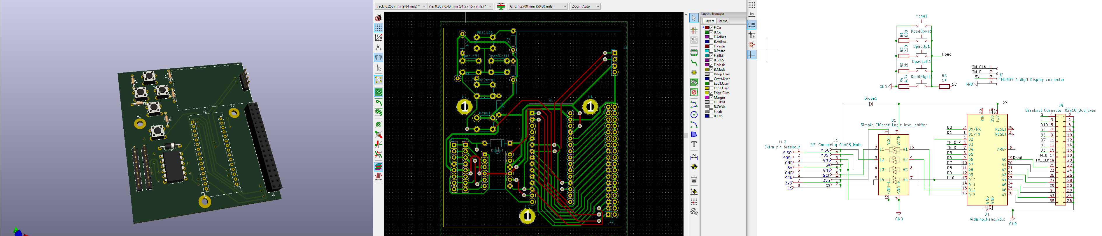
*Updated schematics - Added a 5 buttons Analog input that feeds into a single analog input on the arduino. You can calibrate your wheel center by using the D-pad and alphanumeric display, without plugging the Arduino to your PC!
*Added Diode, and connected D2 and D10 together, both changes are necessary! please revise your board to include these changes if you've built one already!
*Updated board layout - it's possible to either manufacture a single layer board, and solder a few jumper wires for the top layer, or manufacture the complete two-layers board. (I used a CNC machine and milled a single layer board)
This project is donationware, if my work helped you out maybe get me a beer! :)
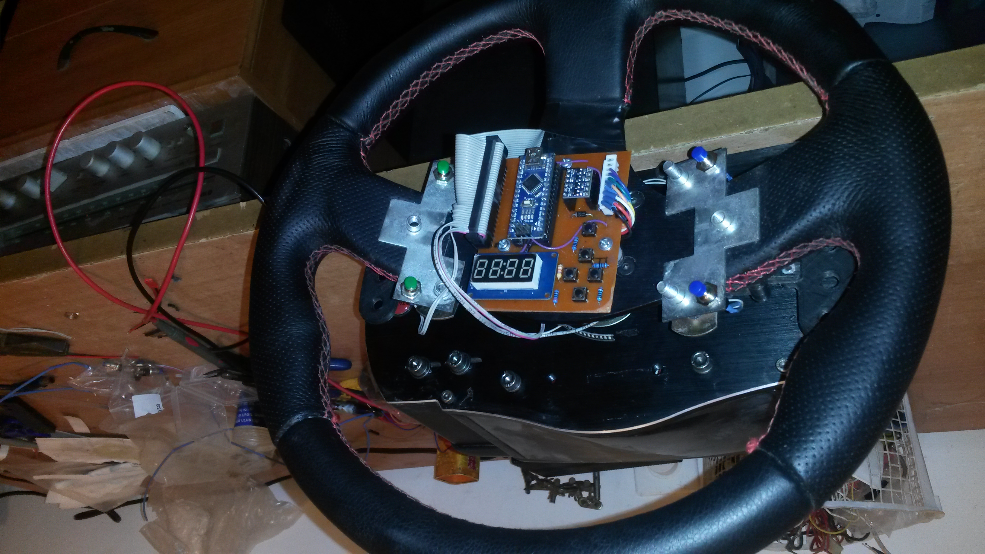
Fanatec's wheelbases won't enable any force feedback, unless you have a Fanatec steering wheel attached to it. With this project, you can use an arduino to communicate with the wheelbase over SPI, which will get the wheelbase working. You can attach buttons, a D-Pad and an alphanumeric display, for the complete package!
This simplified (schematics) version is enough to let you enable force feedback on your wheelbase, use this easy to understand 'breadboard view' simplified schematics, or This simplified schematic.
The full PCB supports alphanumeric display, D-pad, and lots of external buttons
 (I currently use 6: 2 paddle shifters and 4 buttons on the rim).
Here's a how to make a male Fanatec SPI connector (what the steering wheel has)
Also, Alevale found where to buy the connector
use this If you need a simple 3d adapter to attach your physical steering wheel to the wheelbase
- Use a 5V arduino with a logic level shifter. (recommended, this is what I use. (here are The schematics)
- Use a 5V arduino without a logic shifter (can be risky to your precious wheelbase)
- Use a 3.3V arduino (I haven't tried it. They run on 8 MHZ instead of 16 MHZ for the 5V arduinos, but I'm pretty sure 8MHZ should be fast enough.)
Code was tested on arduino Uno and Nano, and works fine. However, they both output 5V and the SPI communication on the wheelbase
is using 3.3V.
It's best to use a level shifter between the two, so there are no chances of damaging the wheelbase (by connecting the 5V arduino
output to a 3.3V wheelbase input)
However, since the wheelbase is the master and the steering wheel is the slave - MISO is the only input channel on the wheelbase,
and it is safe to simply use a voltage divider on the MISO line - to go from 5V level to 3.3V. (The arduino should recognize the 3.3V input signals coming from the wheelbase as high, so there's nothing we have to do there).
- Note: If you do end up going this route, make sure you wire everything up properly, and that you never set SPI as master on the arduino, or you will subject the wheelbase SPI to 5V. (I did subject the wheelbase SPI to 5V by mistake - and nothing got damaged.)
I recommend using an arduino nano and a logic shifter, as seen in the schematics.
- Note: The diode is crucial to keep the 5V coming from the wheelbase, and the 5V coming from the computer USB, seperate. the diode will drop the 5V voltage from the wheelbase to ~4.3V, which is fine for the arduino to run on. When you plug the USB cable, the arduino will run on the 5V coming from the computer, and current cannot flow to the wheelbase because of the diode.
fyi I have connected both power supplies together, and did not have anything go up in smoke. (but this is before I thought about using a diode. DO NOT ATTEMPT THIS YOURSELF.
There's a lot of (old) info here
On some wheelbases, you can do that directly from the Fanatec wheel properties page. unfortunately it doesn't work on my CSW V2.5.
You can use the current code to calibrate the wheelbase's center point. (This is needed after a firmware upgrade for the wheelbase) the arduino will translate the alphanumeric display to letters and send them out to the Serial monitor(!). you will need to type in some commands on the Serial monitor, which will look pretty cypheric to you.
Type these characters on the serial monitor, press [return] after each line:
C (to change bits on the 3rd byte that affects buttons. C=3rd)
6 (to change (raise) the sixth bit on the 3rd byte, which is the menu button. this will cause the alphanumeric display to turn on and the message '5_1' (equivilent to 'S_1' i.e. 'setting 1') will be printed on the serial monitor.)
6 (to release the menu button (lower the 6th bit) )
23 (2 will raise the D-pad button bit, 3 will raise the joystick button bit.)
23 (to release both buttons, drop both bits)
6 (press the menu button again to exit the menu)
6 (release the menu button)
Watch this If you don't know what I'm talking about
(Hey - it's not an easy procedure, but it works!)
if you made a PCB with a Dpad and alphanumeric display - you can calibrate the center point without connecting to the computer!
Using the Dpad:
Enter the menu by pressing both up+down bubttons on the Dpad,
S_1 will appear on the serial monitor and on the alphanumeric display,
Press both left+right buttons on the Dpad to calibrate wheel center,
Press both up+down on the Dpad to exit menu. Done!
This project would never have been possible without the work of Darknao on his BtClubSportWheel - converting any Fanatec CSW steering wheel to a standalone USB version project.