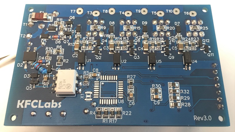
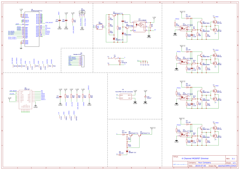
Firmware for a trailing/leading edge dimmer written in C++ including schematics/PCB layouts
- 16666/20000 (60/50Hz) different dimming levels
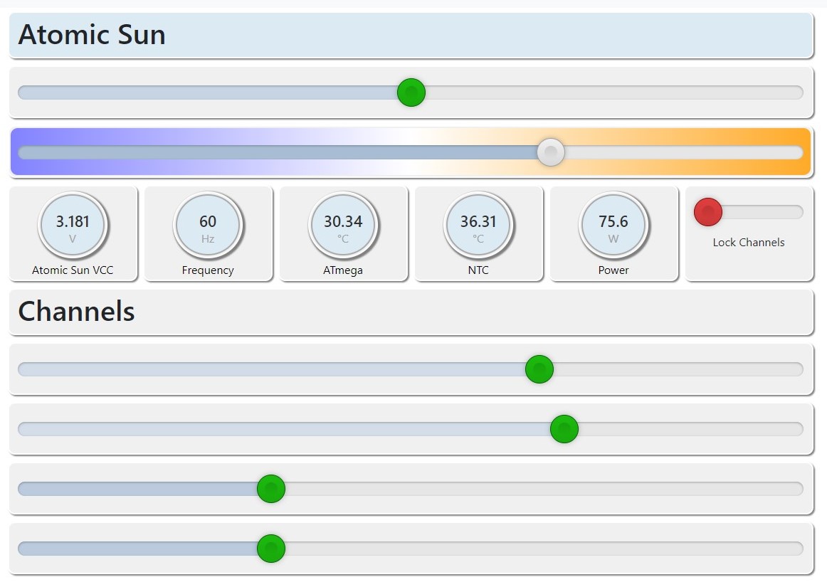
- Up to 8 different channels (16 channels without cubic interpolation and temperature sensing)
- Trailing edge or leading edge mode
- 50/60Hz auto detection
- Store last levels in EEPROM and restore during startup
- EEPROM wear level protection
- Serial protocol to control the dimmer
- I2C or UART interface
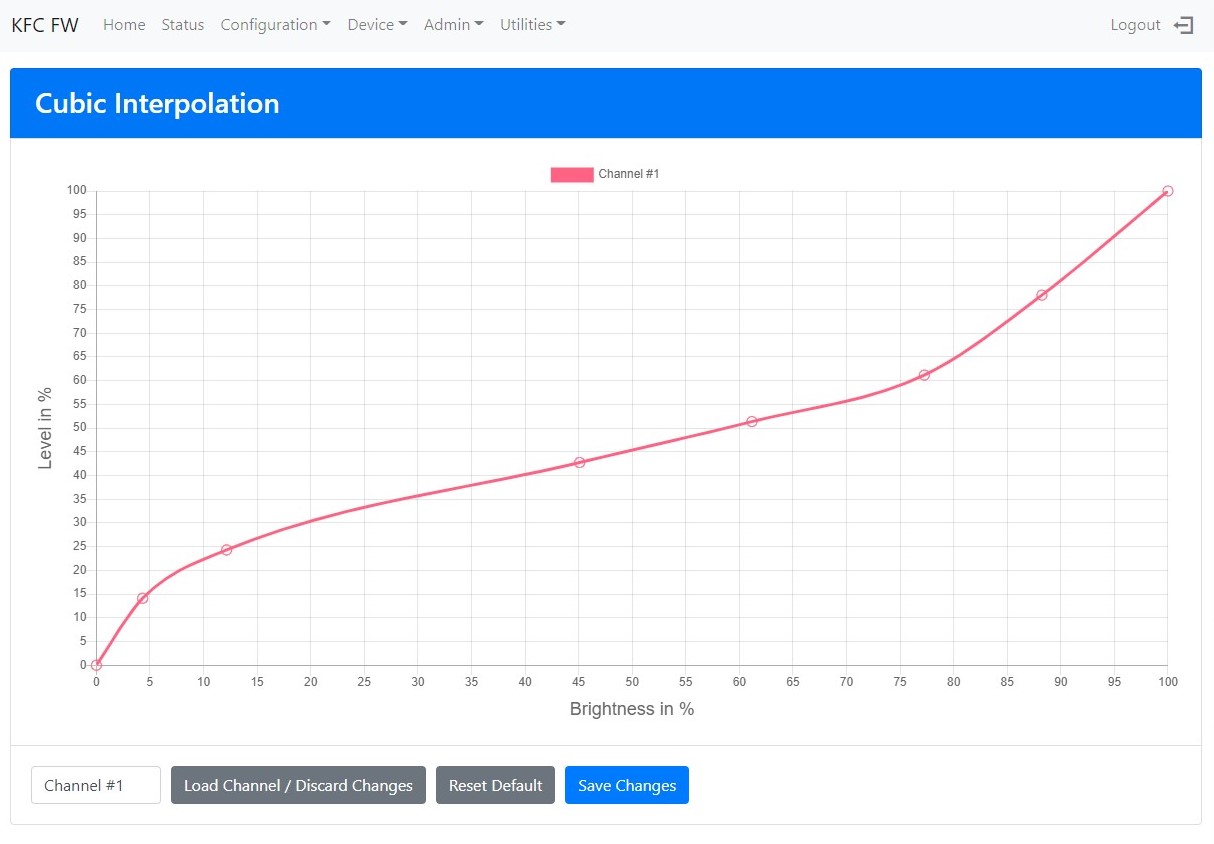
- Cubic interpolation for linear brightness
- Zero crossing filter with predictive error correction
- Support for 10V dimming (or any other voltage in the 0-1.1V range)
- Over temperature protection using an external NTC or the internal ATmega temperature sensor
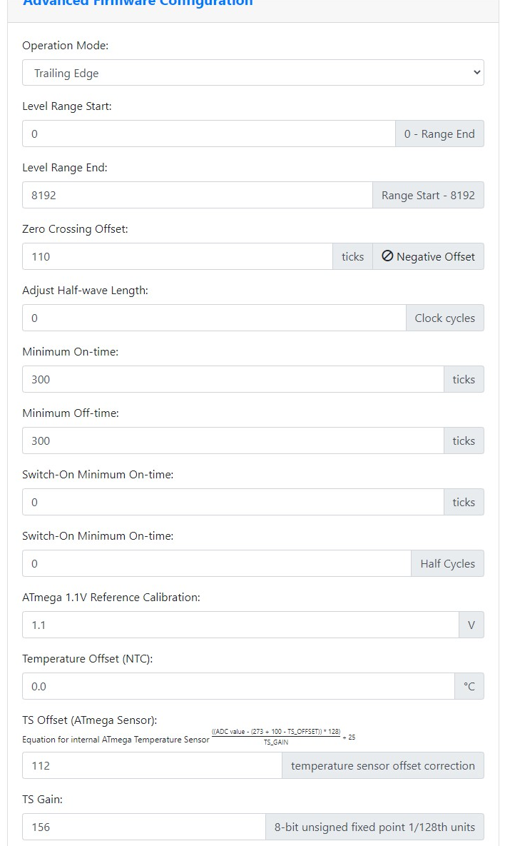
- Highly configurable to match any hardware
- MOSFETs, IGBTs, BJTs and, TRIACs can be used
The Arduino library requires a small patch. While building, an error will show up
File not patched. Run following command:

patch -i ./scripts/Print.diff ~/.platformio/packages/framework-arduino-avr/cores/arduino/Print.h
Execute the command or patch the file by hand, then run the build process again.
The patch adds public 2 methods to the Print class. Those can be used in other projects as well by adding the 3 methods from src/helpers.cpp at the top.
size_t printf(const char *format, ...);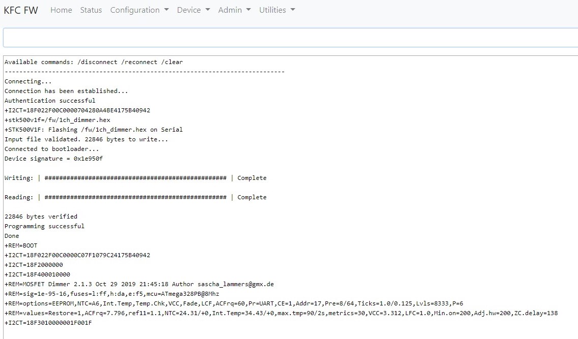
size_t printf_P(PGM_P format, ...);The recent version of the KFC firmware supports programming the ATmega over the STK500v1 protocol directly from the ESP8266. I am using the Arduino bootloader for the ATmega328P mini PRO board@8MHz (ATmegaBOOT_168_atmega328_pro_8MHz.hex)
Since most LEDs do not dim linearly the firmware supports to set up to 8 points which are interpolated to have smooth dimming over the entire range.
The firmware supports trailing and leading edge with MOSFETs and BJTs. With TRIACs, only leading edge is possible. The mode can be changed without upgrading the firmware.
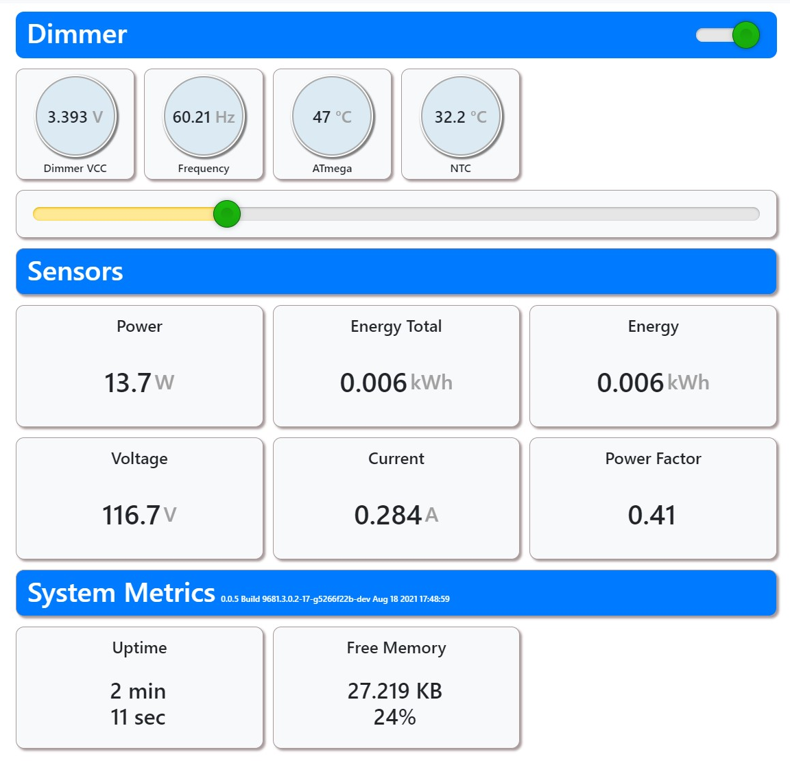
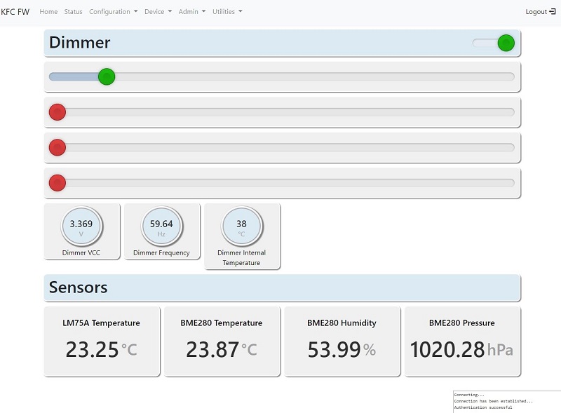
Due to limited space the Energy Monitor is not integrated into the ATmega firmware. It is available for the ESP8266 using the KFC Firmware, which offers an easy way to configure the firmware over a WebUI. Direct access to the I2C or UART is also available. MQTT and Home Assistant are supported.
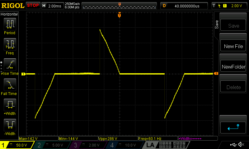
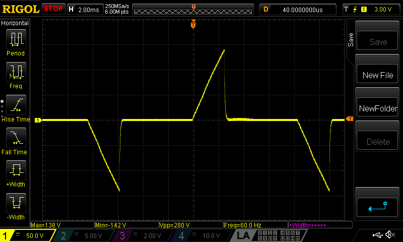
I've improved the zero crossing detection by adding a RC filter, which improves the signal but still has a 0.5% error rate compared to 2.2% before. Software filtering reduces the error rate to 0.001% even without the RC filter.
Test environment: 4x10W LED + 60W incandescent bulb, 50% dimmed, random 1000-2500V transients 5-20µs several times per second on the AC side.

The recent version can lose the zero crossing signal for a couple seconds before it turns the dimmer off. The time can be configured to turn the dimmer off before the signal gets out of sync.
It is highly recommende to use flame retardant ABS or smiliar material that can withstand higher temperatures.
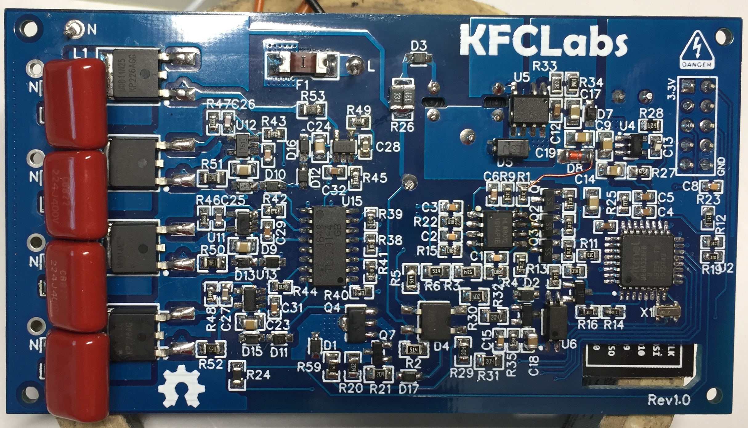
UPDATE: The 4 channel dimmer (Rev1.0) has reached 500kWh without any issues. I am looking forward to see 1.0MWh :)
The LEDs are 20x15W NOMA 052-9892-8 2700K/5000K 1600lm, probably using an non-isolated offline buck driver without power factor correction.
The actual power consumption is over 17.5W and they are getting up to 120°C at the outside with good ventilation. Nothing I can recommend, but they are doing ok temperature wise running at 8-9W and have a good light output when not over-driven.
New version with Energy Monitor
Old version
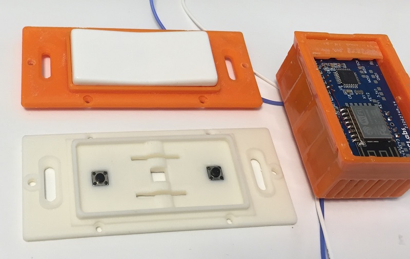
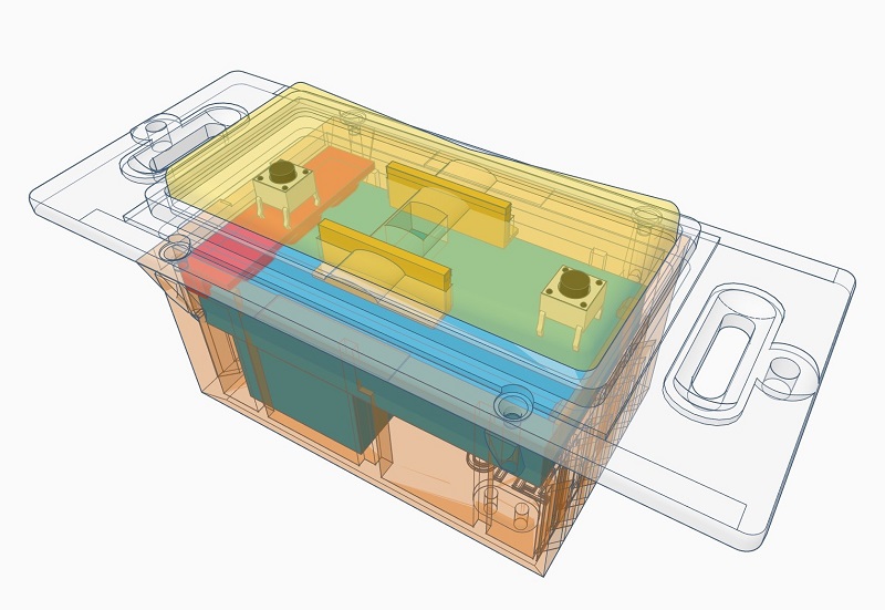
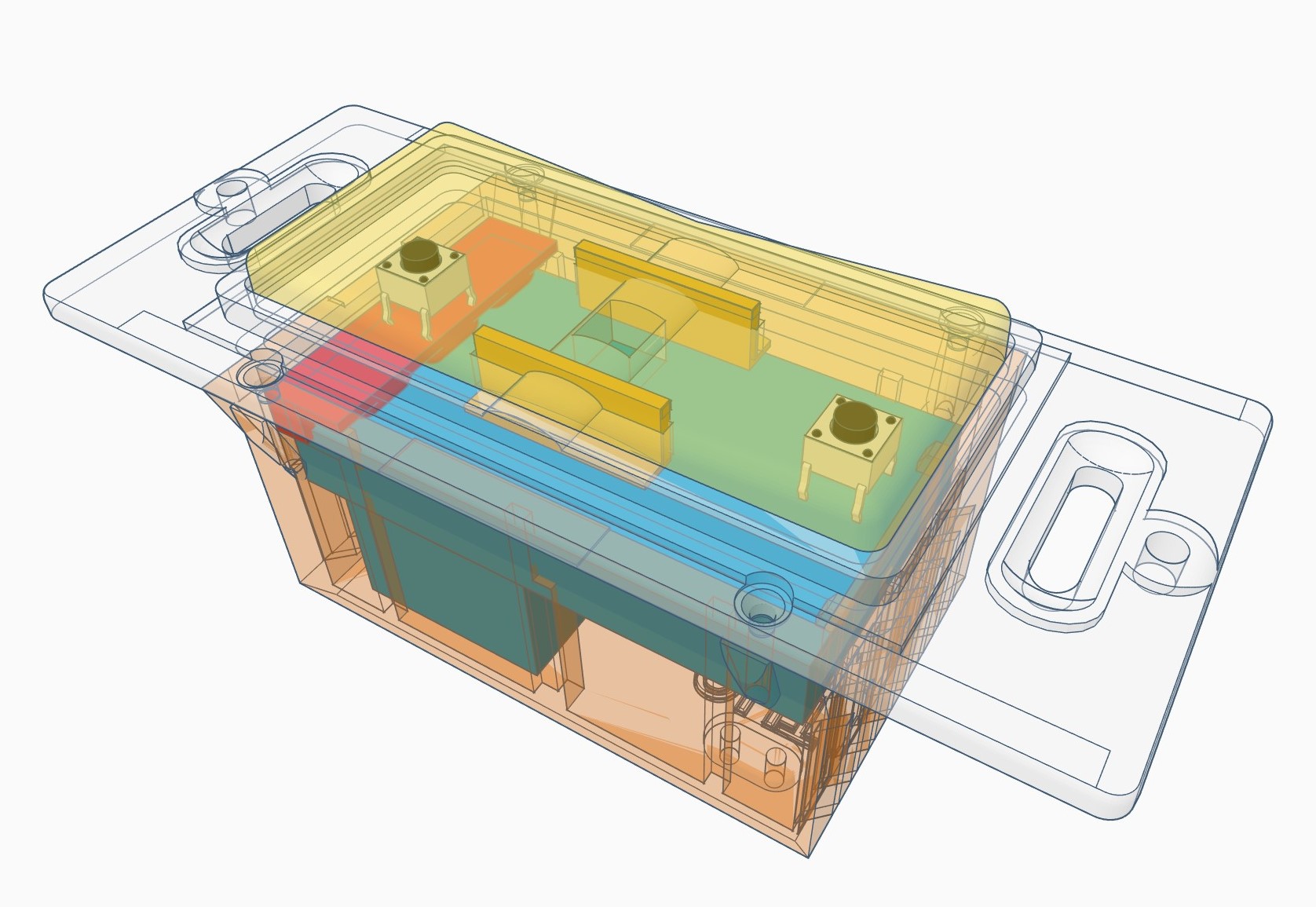
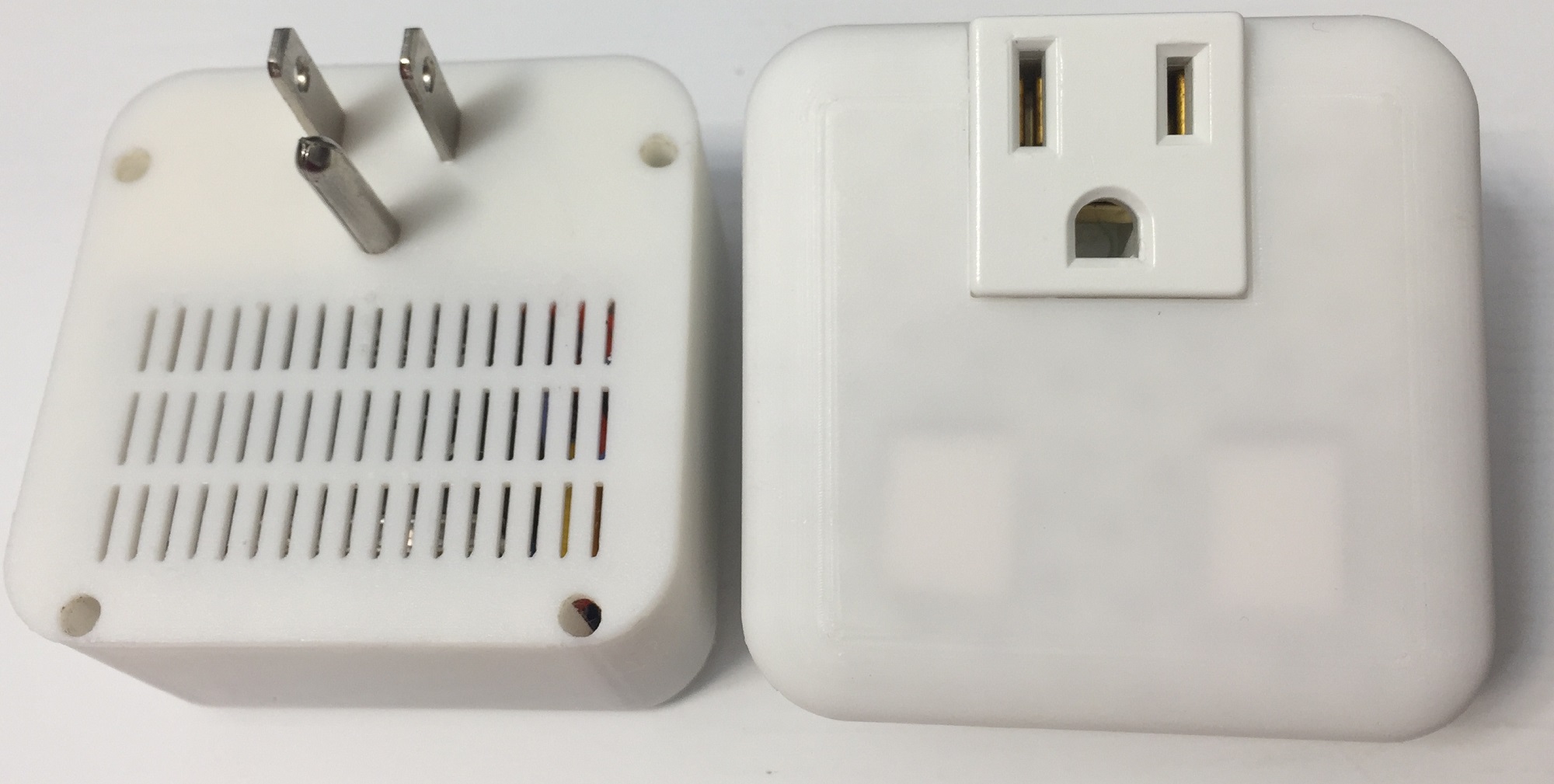
- In-Wall Dimmer
- ESP8266 with MQTT and Home Assistant integration
- Atmega328P as controller over UART
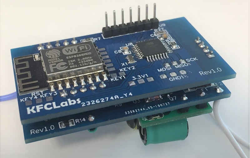
- ESP12E/Atmega328P Control Module
- 1 Channel Dimmer Module
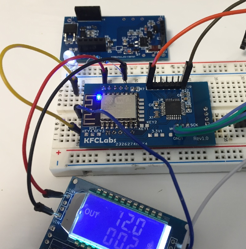
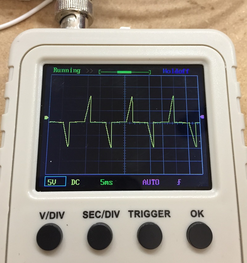
Testing it with a PWM generator to simulate the zero crossing signal, dimming a LED instead switching the MOSFET. The 120V part is waiting for opto couplers.
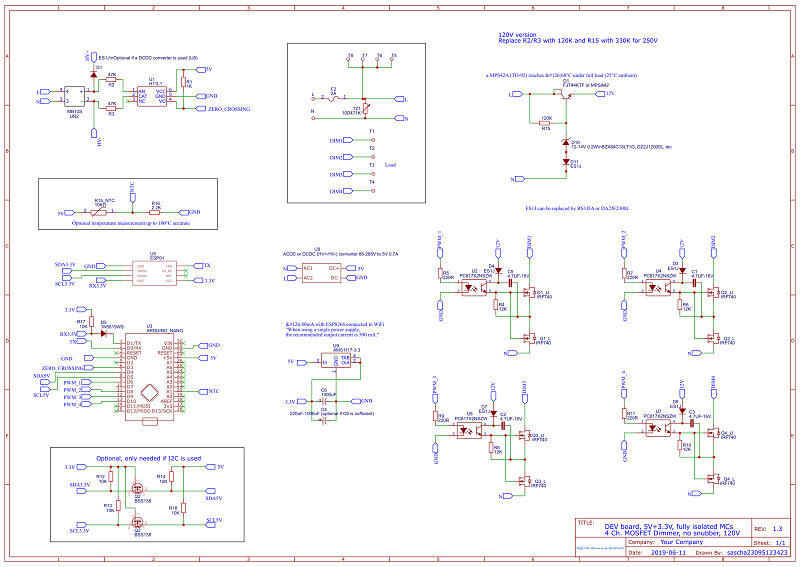
- 3.3V only
- Improved power consumption (~0.3-0.4W idle depending on the power supply)
- Improved MOSFET switching
- Low current consumption (0.15mA @ 120V)
- Tested with 85-265V 50/60Hz
- Logic level output with different opto isolators (4N25, PC817, ACPL-217)
- 50-110us pulse width to extend opto isolator live
UPDATE: I've updated the previous version of the zero crossing detection to support a wide voltage range of 12-265VAC, consuming 2mW-75mW depending on the voltage. The error rate has also been reduced to almost zero. Send me an email if interested.
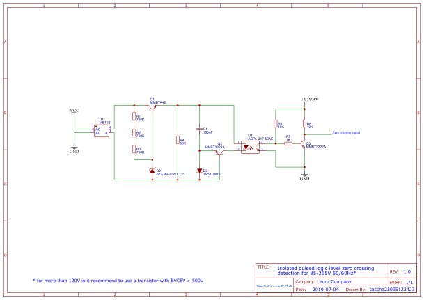
The schematics are for the current zero crossing detection I am using and is different from the picture above.