The USB PD Tester is a monitoring and triggering device designed for USB Power Delivery. It allows you to test a wide range of USB Type-C PD power supplies and their corresponding cables. This tool not only displays the capabilities of the power supply on an OLED but also enables you to select one of the available fixed or programmable voltages for output on the screw terminal. With this, it can also be used to power your projects with various selectable voltages and high currents, serving as a versatile variable power supply.
The USB PD Tester is built around the inexpensive (30 cents at the time of writing) and user-friendly CH32X035 RISC-V microcontroller, which comes with integrated USB 2.0, USB PD 2.0/3.0, and USB Type-C hardware support.
- Project video (Youtube): https://youtu.be/wqLiRnbcISo
USB Power Delivery (USB PD) is a protocol that extends the capabilities of standard USB connections, allowing for faster charging and power delivery between devices. USB PD operates through negotiation between the source and sink devices. They exchange information through PDOs, determining the optimal power level for charging or powering the sink device. PPS enhances flexibility by allowing dynamic adjustments, and CC1 and CC2 are the communication channels involved in the negotiation process:
- Source: The source is a device that provides power, such as a charger or power bank. It can negotiate with the connected device to determine the optimal power level. Here the USB PD power supply to be tested acts as the source.
- Sink: The sink is a device that consumes power, like a smartphone or laptop. It communicates with the source to negotiate the power it needs for charging or other operations. Here the USB PD Tester acts as the sink.
- PDO (Power Delivery Object): A PDO is a data structure exchanged between the source and sink during negotiation. It contains information about the available voltage and current levels. The devices negotiate and agree on a mutually supported PDO for power delivery.
- PPS (Programmable Power Supply): PPS is a feature in USB PD that allows dynamic adjustment of the voltage and current levels during operation. It enables more flexible power delivery based on the specific needs of the connected device.
- CC1 and CC2 (Configuration Channel 1 and 2): These are the communication channels used by USB Type-C connectors for negotiating power delivery. CC1 and CC2 lines carry information about the capabilities of the devices and facilitate negotiation.
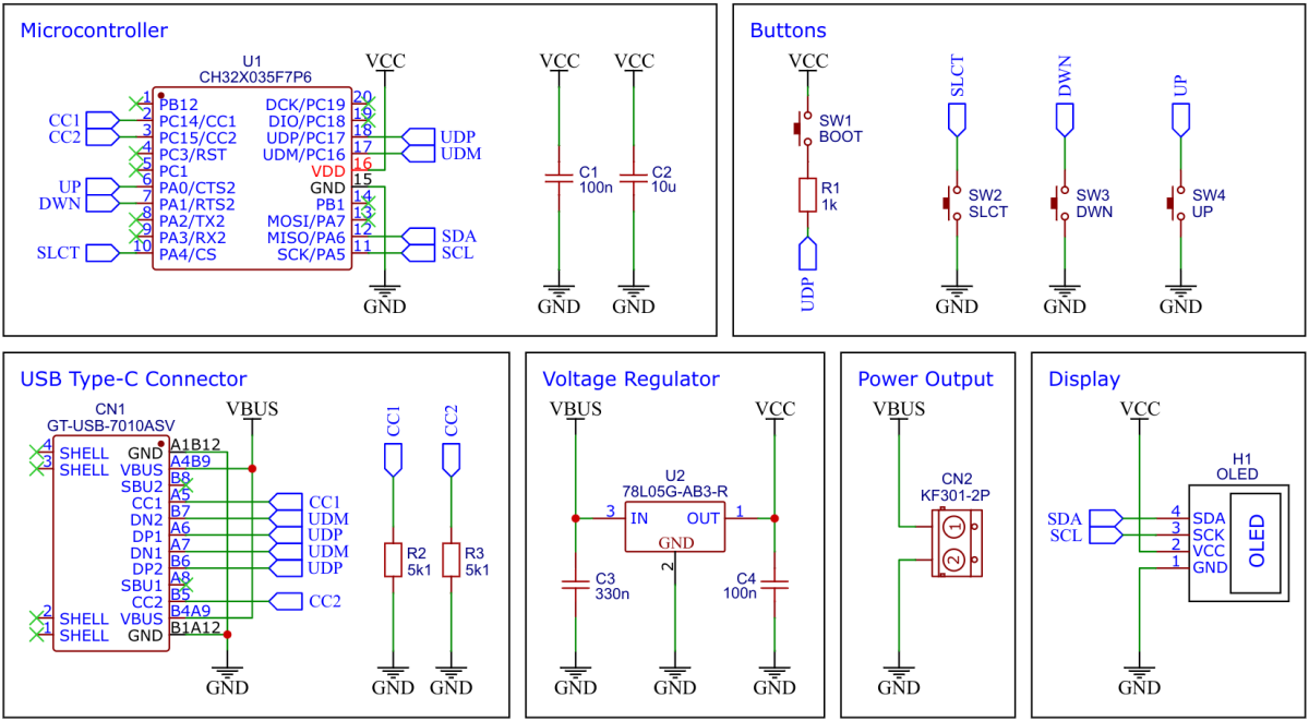
CH32X035F7P6 is a low-cost microcontroller that utilizes the QingKe 32-bit RISC-V4C core, supporting the RV32IMAC instruction set along with self-extending instructions. This microcontroller comes with a built-in USB PHY, supporting USB2.0 full-speed device functions and a USB PD PHY with source and sink capabilities. It features a programmable protocol I/O controller (PIOC), an operational amplifier (OPA) with programmable gain (PGA), an analog comparator (CMP), a 12-bit analog-to-digital converter (ADC), an 11-channel touch-key controller, 3 groups of USART, I2C, SPI, multiple timers, and various other peripheral resources. The device can operate at clock frequencies of up to 48MHz and is compatible with a supply voltage range of 2.0V to 5.5V. The CH32X035F7P6 includes 48KB of flash, 20KB of SRAM, and an embedded USB bootloader.
The 78L05 is a simple and inexpensive voltage regulator that can convert input voltages up to 30V to an output voltage of 5V with an output current of up to 100mA and a dropout voltage of 1.7V. The 78L05 supplies all elements of the circuit with up to 5V.
The GNU Compiler Collection for RISC-V, Python3, and PyUSB must be installed on your system for compiling and flashing. On Linux (Debian-based), all of this can be done with the following commands:
sudo apt install build-essential libnewlib-dev gcc-riscv64-unknown-elf
sudo apt install python3 python3-pip
python3 -m pip install pyusb
On Linux you do not need to install a driver. However, by default Linux will not expose enough permission to upload your code with the USB bootloader. In order to fix this, open a terminal and run the following commands:
echo 'SUBSYSTEM=="usb", ATTR{idVendor}=="4348", ATTR{idProduct}=="55e0", MODE="666"' | sudo tee /etc/udev/rules.d/99-ch55x.rules
echo 'SUBSYSTEM=="usb", ATTR{idVendor}=="1a86", ATTR{idProduct}=="55e0", MODE="666"' | sudo tee -a /etc/udev/rules.d/99-ch55x.rules
sudo udevadm
The bootloader must be started manually for new uploads. To do this, the board must first be disconnected from the USB port. Now press the BOOT button and keep it pressed while reconnecting the board to the USB port of your PC. The chip now starts in bootloader mode, the BOOT button can be released and new firmware can be uploaded via USB within the next couple of seconds.
Open a terminal and navigate to the folder with the makefile. Run the following command to compile and upload:
make flash
If you want to just upload the pre-compiled binary, run the following command instead:
python3 ./tools/chprog.py pd_test.bin
WCH offers the free but closed-source software WCHISPTool to upload firmware with Windows via the USB bootloader. Press the BOOT button and keep it pressed while connecting the board to the USB port of your PC. Release the BOOT button, open the pd_test.hex file in WCHISPTool and upload it to the microcontroller.
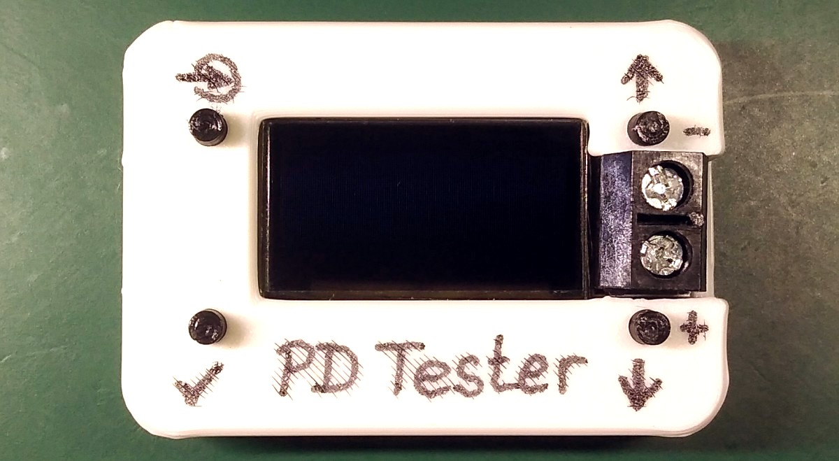
- Print the casing with your 3D printer.
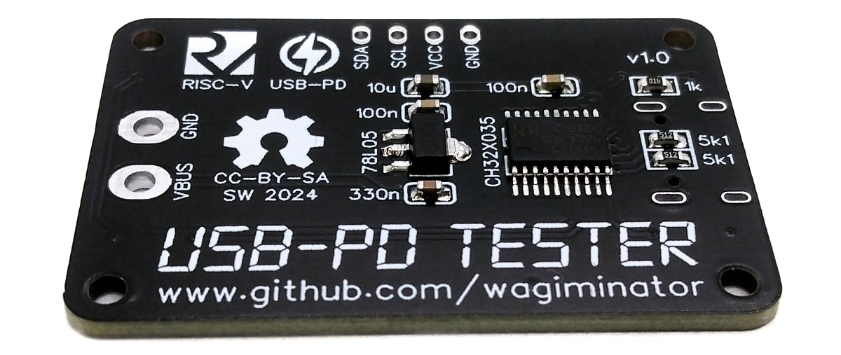
- Solder the components onto the circuit board. Remove the plastic part from the pin header of the OLED, trim the pins, and solder the OLED module flush onto the PCB. Do not solder the screw terminal yet.
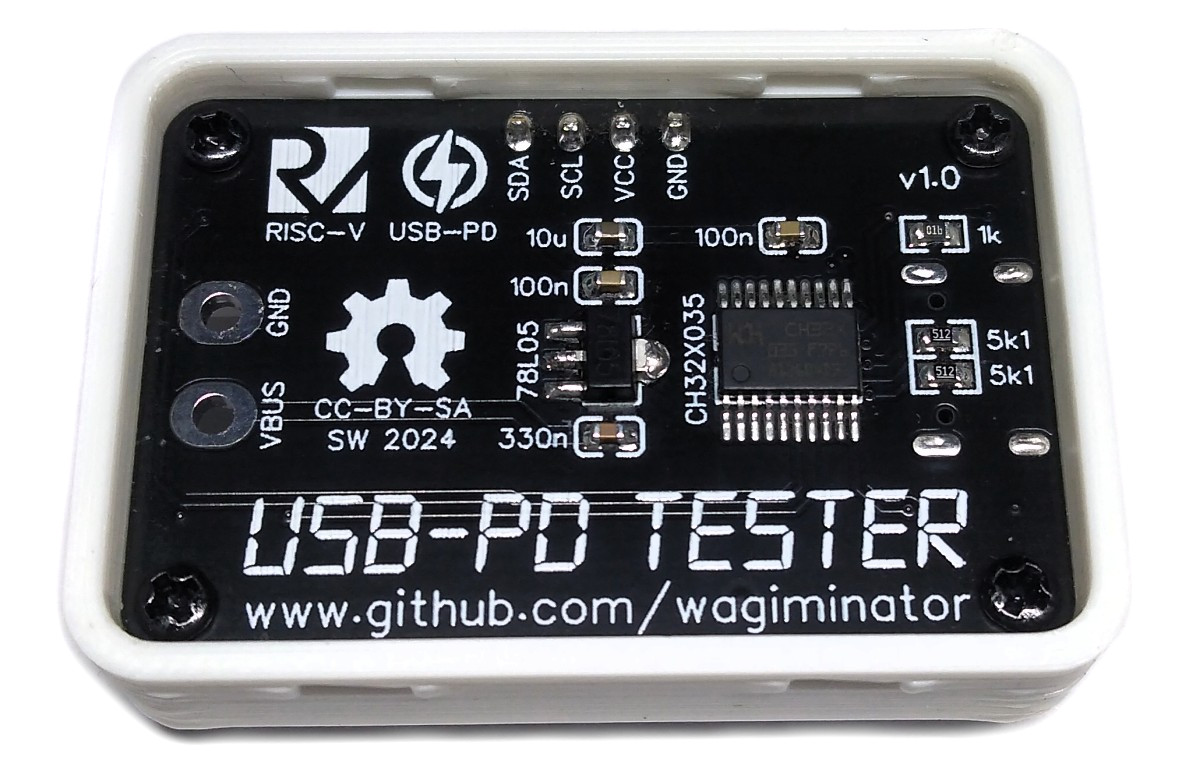
- Insert the button extensions into the corresponding holes on the top part of the casing. Insert the circuit board and secure it with 4 self-tightening M2x5mm screws.
- Now solder the screw terminal onto the circuit board.
- Close the casing with the back panel.
- Flash the firmware (see above).
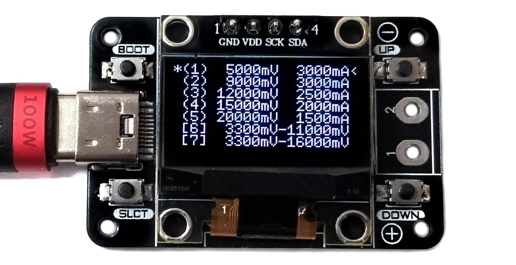
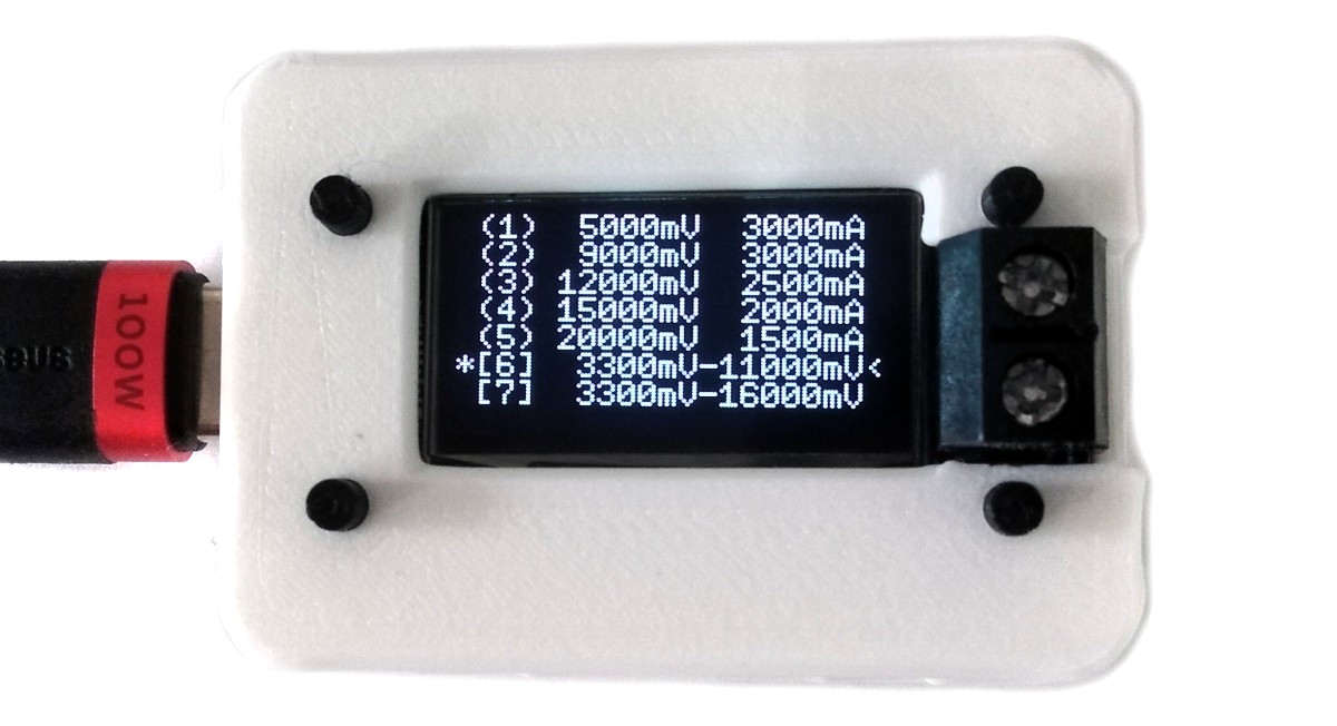
- Connect the USB PD Tester to a USB Type-C PD power supply using a USB-C cable. The available PDOs and their corresponding capabilities are displayed on the OLED.
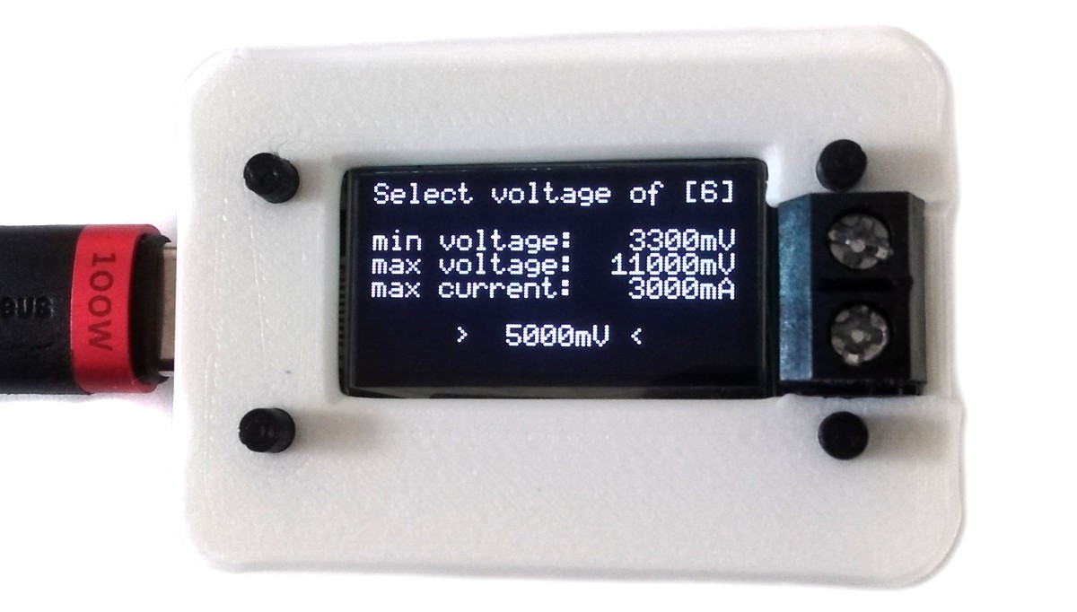
- Utilize the UP and DOWN buttons to choose the desired PDO. A left-angle bracket on the right side serves as the selection indicator. Programmable PDOs, indicated by numbers within square brackets, allow precise adjustments of the output voltage in 20mV steps within the specified range.
- Press the SLCT button to activate the chosen PDO. An asterisk on the left side of the PDO confirms the activation.
- The selected voltage is now accessible on the screw terminal for further use.
- EasyEDA Design Files
- MCU Templates
- MCU Flash Tools
- CH32X035 Datasheets
- SSD1306 Datasheet
- 78L05 Datasheet
- ATtiny814 USB PD Adapter
- ATtiny412 USB PD Inverter
- TI Primer on USB PD
- CH32X035 F7P6 on Aliexpress
- 128x64 OLED on Aliexpress

This work is licensed under Creative Commons Attribution-ShareAlike 3.0 Unported License. (http://creativecommons.org/licenses/by-sa/3.0/)